SMC Controllers Bulletin 150 Application and Product Guide
Please Read! This manual is intended to guid qualified personnel in th installation and operation of this product. Because of the variety of uses for this equipment and because of the differences between this solid-state equipment and electromechanical equipment, the user of and those responsible for applying this equipment must satisfy themselves as to the acceptability of each application and use of the equipment. In no event will Allen-Bradley Company, Inc.
Table of Contents Chapter 1 STC Starting Torque Controller Description . . . . . . . . . . . . . . . . . . . . . . . . . . . . . . . . . . Modes of Operation . . . . . . . . . . . . . . . . . . . . . . . . . . . . Across-the-Line Response . . . . . . . . . . . . . . . . . . . . . STC Controller Response . . . . . . . . . . . . . . . . . . . . . . Across-the-Line Response Versus STC Controller Response . . . . . . . . . . . . . . . . . . . . . . . Features . . . . . . . . . . . . . . . . . . . . . . . . . .
toc–ii Table of Contents Chapter 3 (cont.) Features . . . . . . . . . . . . . . . . . . . . . . . . . . . . . . . . . . . . . LCD Display . . . . . . . . . . . . . . . . . . . . . . . . . . . . . . . . Keypad Programming . . . . . . . . . . . . . . . . . . . . . . . . . Electronic Overload . . . . . . . . . . . . . . . . . . . . . . . . . . . Built-in Communication Port . . . . . . . . . . . . . . . . . . . . Stall Protection and Jam Detection . . . . . . . . . . . . . . . Phase Rebalance . . . . . . . .
toc–iii Table of Contents Chapter 5 SMC Dialog Plus Controller Special Application Considerations SMC Dialog Plus Controllers in Drive Applications . . . . . . Use of Protective Modules . . . . . . . . . . . . . . . . . . . . . . . Current Limit Fuses (Overcurrent Protection of SCRs) . . . Motor Overload Protection . . . . . . . . . . . . . . . . . . . . . . . . Phase Rebalance . . . . . . . . . . . . . . . . . . . . . . . . . . . . . . Stall Protection and Jam Detection . . . . . . . . . . . . . . . . .
toc–iv Table of Contents Chapter 7 Design Philosophy Philosophy . . . . . . . . . . . . . . . . . . . . . . . . . . . . . . . . . . . Line Voltage Conditions . . . . . . . . . . . . . . . . . . . . . . . . . Current and Thermal Ratings . . . . . . . . . . . . . . . . . . . . . Mechanical Shock and Vibration . . . . . . . . . . . . . . . . . . . Set-up . . . . . . . . . . . . . . . . . . . . . . . . . . . . . . . . . . . . . .
Table of Contents toc–v Chapter 10 (cont.) Engineering Constants . . . . . . . . . . . . . . . . . . . . . . . . . . 10-19 Temperature . . . . . . . . . . . . . . . . . . . . . . . . . . . . . . . . 10-19 Length . . . . . . . . . . . . . . . . . . . . . . . . . . . . . . . . . . . . 10-19 Weight. . . . . . . . . . . . . . . . . . . . . . . . . . . . . . . . . . . . .10- 20 Power . . . . . . . . . . . . . . . . . . . . . . . . . . . . . . . . . . . . . 10-20 Area . . . . . . . . . . . . . . . . . . . . . .
SMC Controllers The Allen-Bradley SMC Controller lines offer a broad range of products for starting or stopping AC induction motors from 1/3 HP to 6,000HP. The innovative features, compact design, and available enclosed controllers meet world-wide industry requirements for controlling motors.
Chapter 1 STC Starting Torque Controller Description The STC Starting Torque Controller is designed for low horsepower single-phase and three-phase squirrel cage induction motors. It is intended to relieve the starting torque surge encountered in typical across-the-line starting. This will provide smoother starts and decrease downtime due to shock and vibration related problems.
1-2 STC Starting Torque Controller Modes of Operation Across-the-Line Response Excessive motor starting torque can damage the motor and driv equipment. Figure 1.2 illustrates the torque developed in a typical across-the-line start. Figure 1.2 Torque Developed in a Typical Across-the-Line Start 10 75 50 Torque NM 25 0 -25 -50 0 0.1 0.2 0.3 0.4 0.5 0.6 0.7 Time (sec.) STC Controller Response The STC controller reduces the magnitude of starting torque surges as illustrated in Figure 1.3.
1-3 STC Starting Torque Controller Features The STC controller is a compact device with feed through wiring for ease of installation. To set up the controller, adjust the digital rotary switches. The initial torque value is set between 10 and 80% of locked rotor torque. The voltage ramp time is adjustable from 0.1 to 4.5 seconds. This flexible combination enables the STC controller to be installed in a wide variety of applications. Adjustments Figure 1.
1-4 STC Starting Torque Controller Wiring Diagrams Figure 1.6 Typical Wiring Diagrams for STC Controller in Three-phase Applications M L1/1 T1/2 L2/3 T2/4 L3/5 T3/6 Power Input 3-Phase Branch Protection ➀ Stop ➀ Existing Motor Starter ➀ Start ➀ ➀ M➀ Motor ➀ Starting Torque Controller O.L. ➀ Existing Control Circuit M ➀ Customer supplied Figure 1.
1-5 STC Starting Torque Controller Figure 1.8 Typical Wiring Diagrams for STC Controller – Reversing F L1/1 T1/2 L2/3 T2/4 L3/5 T3/6 Power Input 3-Phase R Branch Protection ➀ Stop ➀ Forward ➀ F➀ Overload Rela (O.L.) ➀ R➀ F Motor ➀ Starting Torque Controller O.L.
1-6 STC Starting Torque Controller Suitable Replacement Applications The STC controller is a suitable replacement for: • Wye-delta Starters • Resistor Ballast Starters • Line Reactors • Clutches • Flywheels • Fluid Couplings • Other Mechanical and Electrical Soft Start Devices In this section a few of the many STC controller applications are described. Illustrations are included to help identify the particular application.
STC Starting Torque Controller Applications (cont.) 1-7 Figure 1.9 Chair Elevator Problem: A single-phase chain driven chair elevator was started across-the-line. The starting torque caused the chair to lurch during the start and occasionally caused chain alignment problems. Solution: An STC controller was installed to provide controlled acceleration.This minimized the mechanical shock encountered during across-the-line starting and reduced alignment problems.
1-8 STC Starting Torque Controller Applications (cont.) Figure 1.10 Paint Shaker Problem: The commercial paint shaker was operated with a single phase motor and used across-the-line starting. This method of starting caused the facility’s line voltage to dip. The building’s fluorescent lighting, with electronic ballasts, was extremely sensitive to line voltage dips and would momentarily shut off when the paint shaker was started.
1-9 STC Starting Torque Controller Figure 1.11 Chain Conveyor with Torque Control 480 Volts 7.5 HP Bundle Bundle Chain Motor Problem: A chain conveyor is used for transporting bundles of paper. Due to the high starting torque the conveyor motor applies to the chain during startup, the chain was breaking on an average of once per day. Maintenance of the conveyor caused interruptions in the production schedule.
1-10 STC Starting Torque Controller Applications (cont.) Figure 1.12 Crane with Torque Control 480 Volts 2 HP Traverse Motor (STC Controlled) Track Load Problem: An overhead crane required frequent jogging due to adjustments in the traverse (horizontal) position. An across-the-line starter was used and this caused overshoot or undershoot when trying to position over a load. Solution: The STC controller was installed in the application.
1-11 STC Starting Torque Controller Figure 1.13 Aircraft Hangar Door 480 Vol 2 Hp Chain Motor Problem: A chain driven aircraft hangar door was started acrossthe-line. The starting torque caused chain alignment problems. This required frequent inspection and maintenance. Solution: An STC controller was installed to provide controlled acceleration. This minimized the mechanical shock encountered during across-the-line starting and reduced maintenance inspection.
Chapter 2 SMC-2 Smart Motor Controller Description The SMC-2 Smart Motor controller is a compact, multi-functional solid state controller used in starting standard three-phase squirrel cage induction motors and controlling resistive loads. The SMC-2 product line includes current ranges from 5–97 Amps, 200 to 600V, 50/60 Hz., UL Listed, CSA Approved, and CE labeled. This covers applications up to 75 horsepower. Figure 2.
2-2 SMC-2 Smart Motor Controller Modes of Operation (cont.) Soft Start This is the most common method of starting. The initial torque value is set between 0–70% of locked rotor torque. The motor voltage is steplessly increased during the acceleration ramp period, which is adjustable from 2–30 seconds. Figure 2.2 Soft Start 100% Percent Voltage Initial Torque Start Run Time (seconds) Current Limit Start This starting mode is used when it is necessary to limit the maximum starting current.
SMC-2 Smart Motor Controller 2-3 Full Voltage Start This mode is used in applications requiring across-the-line starting. The ramp time is less than 1/10 second. Figure 2.4 Full Voltage Start 100% Percent Voltage Time (seconds) Features Fault Trips There is a single red LED on the front of the SMC-2 controller for diagnostic indication. When three-phase power is applied to the controller, the LED will be on.
2-4 SMC-2 Smart Motor Controller Adjustments Figure 2.5 SMC-2 Soft Start Mode Selec Time Select Initial Torque Leve Full Voltage Start Starting Time Current Limit Starting Time Energy Saver Select (ON/OFF) Starting Time 50/60 H (ON/OFF) Soft Stopping Time (Active only with interface option) Auxiliary Contact (Up-to-Speed./Instant.
2-5 SMC-2 Smart Motor Controller Figure 2.6 SMC-2 Current Limit Selection OFF Position Time Select Current Limit Starting Time Energy Saver Select (ON/OFF) 50/60 H (ON/OFF) Auxiliary Contact (Up-to-Speed./Instant.
2-6 SMC-2 Smart Motor Controller Adjustments (cont.) Figure 2.7 SMC-2 Full Voltage Selection Time Select Full Voltage Starting Time Current Limit Starting Time Energy Saver Select (ON/OFF) Starting Time 50/60 H (ON/OFF) v Auxiliary Contact (Up-to-Speed./Instant.
2-7 SMC-2 Smart Motor Controller Wiring Diagram Series Controller The SMC-2 controller is designed to operate with an electromechanical starter. The series mode has the following features: • Simplified initial installation – no need for additional wiring • Easy retrofits – works with existing electromechanical starter Figure 2.8 Wiring Diagram for Series Controller M L1/1 T1/2 L2/3 T2/4 L3/5 T3/6 Power Input 3-Phase Branch Protection ➀ Stop ➀ Overload Relay (O.L.
2-8 SMC-2 Smart Motor Controller Options Description of Interface Options The SMC-2 controller is designed to be operated by an external device. An optional interface is available for the SMC-2 controller. This offers the following features: • ON/OFF control directly to the controller through an external device. In many applications the interface may eliminate the need for an additional contactor. This reduces the panel space required.
2-9 SMC-2 Smart Motor Controller Wiring Diagram with Interface Option Control power requirement for the interface option is 5VA at 120V and15VA at 240V. Auxiliary contact rating is NEMA C300, 2.5 Amps, 20–250V AC: 1 Amp, 12–30V DC. Figure 2.11 Wiring Diagram with Interface Option L1/1 T1/2 L2/3 T2/4 L3/5 T3/6 Power Input Motor ➀ 3-Phase Branch Protection ➀ Overload Relay (O.L.) ➀ SMC-2 Controlle C.C.T. ➀ ➀ Stop ➀ ➂ 10 Start ➀ 20 O.L.
2-10 SMC-2 Smart Motor Controller Options (cont.) Overload Relay Option To save additional panel space, IEC overload relays may be mounted directly to the 5, 9, and 16 Amp SMC-2 controllers. Figure 2.12 SMC-2 Controller with Bulletin 193 Overload Relay (5–16 Amps) Applications In this section a few of many applications are described, as well as why the particular control method was selected. For example, tumbler drum is described using a soft start feature.
SMC-2 Smart Motor Controller 2-11 Figure 2.13 Conveyor with Soft Start 480 Vol 7.5 HP LOG LOG Motor Chain Problem: A conveyor is used to transport logs. The drive chain was breaking due to uncontrolled start-up. This caused interruptions in the production schedule and lost productivity. Panel space was very limited. Solution: Due to its compact design, the SMC-2 controller was easily installed in the space vacated by the previous starter. A 10-second soft start was selected.
2-12 SMC-2 Smart Motor Controller Applications (cont.) Figure 2.14 Tumbler with Soft Start 480 Volts 50 HP Loading Door Drive Chain Tumbler Drum Motor Problem: A tumbler used in a nail finishing process was breaking the drive chain due to the uncontrolled acceleration from the across-the-line start. In addition, a reversing starte was needed to position the drum to the top position for loading the product. Due to lack of controlled acceleration, numerous jogs were used to position the drum.
2-13 SMC-2 Smart Motor Controller Figure 2.15 Power Walk with Soft Start and Soft Stop Option 240 Volts 15 HP Motor Problem: A power walk at an airport required a soft start to prevent damage to the drive chain gearbox on start-up. A soft stop was also required in case the power walk would b shut off while people were still on the belt. There would be multiple units at the site, and a controller that could be quickly installed and adjusted was required.
2-14 SMC-2 Smart Motor Controller Applications (cont.) Figure 2.16 Towline Conveyor with Soft Start and Soft Stop Option 480 Volts 15 HP Pallet Load Load Gearbox Motor Problem: A towline conveyor at the end of a production line had frequent damage to the gearbox due to the starting torque from across-the-line starting of the motor. There were frequent spills on both starting and stopping of the conveyor system. Solution: The SMC-2 controller with the Interface option was installed.
2-15 SMC-2 Smart Motor Controller Figure 2.17 Bottle Filler with Soft Start and Soft Stop Option 480 Volts 1 HP Filler Problem: A bottle filler line had product spillage upon starting and stopping. An across-the-line starter was used to start th motor. In addition, the application required an auxiliary contact that would energize when the motor was up to speed. Solution: The SMC-2 controller was installed and set for a 10second soft start with a 20-second soft stop.
2-16 SMC-2 Smart Motor Controller Applications (cont.) Figure 2.18 Grinder with Soft Start 575 Volts 20 HP Grinding Wheel Gearbox Motor Problem: Due to the high starting torque developed from starting the motor across-the-line, the gears driving a grinding wheel were frequently damaged. This resulted in unscheduled downtime for repair. This application required a rugged device because vibration at the control panel was a problem.
SMC-2 Smart Motor Controller 2-17 Figure 2.19 Passenger Elevator Problem: A passenger elevator in a parking structure required a soft start to eliminate the jolt which occurred during an across-the-line start. Due to the size of the enclosure, the soft starter must fit in the space vacated by the electromechanical motor starter. Solution: An SMC-2 controller with the Interface option was installed. The starting time was set for 10 seconds.
2-18 SMC-2 Smart Motor Controller
Chapter 3 SMC Dialog Plus Smart Motor Controller Description When the Smart Motor Controller (SMC) was first introduced in 1986, its modular design, digital set-up, and microprocessor control set the standard for soft starters. Since its launch in 1989, the SMC PLUS controller has been in a class by itself, providing unmatched performance with innovative starting and stopping options.
3-2 SMC Dialog Plus Smart Motor Controller Starting Methods The following starting methods are standard within the controller: • Soft Start with Selectable Kickstart • Current Limit Start • Dual Ramp Start • FullVoltage Start Optional features include: • Soft Stop • Pump Control • Preset Slow Speed • SMB Smart Motor Brake • Accu-Stop/Slow Speed with Braking Soft Start with Selectable Kickstart This method has the most general application.
SMC Dialog Plus Smart Motor Controller 3-3 Current Limit Start This starting method provides a fixed reduced voltage start and is used when it is necessary to limit the maximum starting current. Th starting current is user adjustable from 50 to 600% of full load amperes. The current limit starting time is user adjustable from 0 to 30 seconds. Figure 3.
3-4 SMC Dialog Plus Smart Motor Controller Starting Methods (cont.) Full Voltage Start This method is used in applications requiring across-the-line starting. The SMC Dialog Plus controller performs like a solid-state contactor. Full inrush current and locked rotor torque are realized. Figure 3.
SMC Dialog Plus Smart Motor Controller 3-5 Electronic Overload The SMC Dialog Plus controller meets applicable requirements as motor overload protective device. Overload protection is accomplished electronically through an I2t algorithm. The overload is programmable, providing the user with flexibility. The overload trip class is selectable for class 10, 15, 20, or 30 protection. The trip current is set by entering the motor’s full load current rating and the service factor.
3-6 SMC Dialog Plus Smart Motor Controller Features (cont.) Stall Protection and Jam Detection Motors can experience locked rotor currents and develop maximum torque in the event of a stall (during start) or a jam (after full speed is reached). These conditions can result in winding insulation breakdown or mechanical damage to the connected load. The SMC Dialog Plus controller provides both stall and jam detection for enhanced motor and system protection.
3-7 SMC Dialog Plus Smart Motor Controller Phase Rebalance As little as 4% supply voltage unbalance can result in a 20% current unbalance and a 25% increase in motor temperature, possibly triggering a premature failure of the motor. The SMC Dialog Plus controller continuously monitors the incoming three-phase line voltage balance and adjusts the output voltage automatically to balance the three-phase currents drawn by the motor. Figure 3.
3-8 SMC Dialog Plus Smart Motor Controller Features (cont.) Auxiliary Contacts Three hard contacts are provided as standard with the SMC Dialog Plus controller. The first two contacts are programmable for Normal/ Up-to-speed. The third contact is programmable for Normal/Fault. Energy Saver The built-in Energy Saver feature is integral to the SMC Dialog Plus controller and may be applied to applications where the motor is lightly loaded or unloaded for long periods of time.
SMC Dialog Plus Smart Motor Controller 3-9 Control Terminal Description The SMC Dialog Plus controller contains 20 control terminals on the front of the controller. These control terminals are described below. See Figure 3.11. Power Supply Board Terminal Number Description 11 Control Power Input 12 Control Power Common 13 Controller Enable Input 14 Logic Ground 15 Dual Ramp/Option Input 16 Start Input 17 Stop Input 18 Auxiliary Relay Common 19 N.O.
3-10 Adjustments SMC Dialog Plus Smart Motor Controller Soft Start without Options The following parameters are specifically used to provide and adjust the voltage ramp supplied to the motor Parameter Range Starting Mode This must be programmed for “Soft Start.” Soft Start, Current Limit Ramp Time #1 This sets the time period during which the controller will ramp the output voltage.
3-11 SMC Dialog Plus Smart Motor Controller Current Limit Start without Options To apply a fixed reduced voltage output to the motor, the following parameters are provided for user adjustment. Parameter Range Starting Mode This must be programmed for “Current Limit.” Soft Start, Current Limit Ramp Time #1 This sets the time period during which the controller will hold the fixed reduced voltage output before switching to full voltage.
3-12 SMC Dialog Plus Smart Motor Controller Adjustments (cont.) Dual Ramp Start without Options The SMC Dialog Plus controller provides the user with the ability to select between two soft start profiles. To obtain Dual Ramp Start control, the following parameters are available in the “Advanced Setup” programming mode. Note: The Dual Ramp Start feature is only available with the standard control module.
3-13 SMC Dialog Plus Smart Motor Controller Dual Ramp Start without Options (cont.) Parameter Range Stall Delay Allows the user to program the stall protection delay time. The delay time begins after the start time has timed out. 0 to 10 seconds Energy Saver The Energy Saver feature monitors the motor load, phasing back the voltage output to the motor when the motor is lightly loaded or unloaded for an extended period of time.
3-14 SMC Dialog Plus Smart Motor Controller Adjustments (cont.) Full Voltage Start without Options The SMC Dialog Plus controller may be programmed to provid full voltage start in which the output voltage to the motor reaches full voltage in 1/4 second. Parameter Range Start Mode This must be programmed for “Soft Start.” Soft Start, Current Limit Ramp Time #1 This must be programmed for “0” seconds. 0 to 30 seconds Initial Torque #1 This must be programmed for 90% of locked rotor torque.
3-15 SMC Dialog Plus Smart Motor Controller Typical Wiring Diagrams (without options) Figure 3.12 Typical Wiring Diagram for Standard Controller L1/1 T1/2 L2/3 T2/4 L3/5 T3/6 3-Phase M➀ Input Power Fast-acting SCR Fuses (optional) ➀ ➀ Branch Protection ➀ ➀ ➀ Stop ➀ Start ➀ ➁ 11 12 13 14 15 16 17 18 19 20 Internal Auxiliary Contacts 21 22 23 24 25 26 27 28 29 30 ① Customer supplied.
3-16 SMC Dialog Plus Smart Motor Controller Typical Wiring Diagrams (without options) Figure 3.13 Typical Wiring Diagram for Dual Ramp Applications Control Power ➁ Stop ➀ Ramp 1 ➀ Ramp 2 Start ➀ 11 12 13 14 15 16 17 18 19 20 SMC Dialog Plus Control Terminals Internal Auxiliary Contacts 21 22 23 24 25 26 27 28 29 30 ① Customer supplied. ② Refer to the controller nameplate to verify the rating of the control power input voltage.
3-17 SMC Dialog Plus Smart Motor Controller Figure 3.14 Typical Wiring Diagram for Start-Stop Control via the SCANport Control Power ➁ ➂ 11 12 13 14 15 16 17 18 19 20 21 22 23 24 25 26 27 28 29 30 ① Customer supplied. ② Refer to the controller nameplate to verify the rating of the control power input voltage. ③ If Soft Stop, Pump Control, or SMB Smart Motor option is installed, place additional jumper to terminal 15.
3-18 SMC Dialog Plus Smart Motor Controller Typical Wiring Diagrams (without options) (cont.) Figure 3.15 Typical Wiring Diagram for Retrofit Applications 3-Ph as e L1/1 T1/2 L2/3 T2/4 L3/5 T3/6 Inpu t Pow er Bran ch Protection ➀ M➀ Fast-acting Ex is ting M otor S CR Fu ses S tarter➀ (O ption al) ➀ ➀ OL M S tart➀ S top ➀ M➀ ➁ 11 12 13 14 15 16 17 18 19 20 21 22 23 24 25 26 27 28 29 30 ① Customer supplied.
3-19 SMC Dialog Plus Smart Motor Controller Control Options The SMC Dialog Plus controller offers a variety of unique control options that provide enhanced motor starting and stopping capabilities. Please note that the options are mutually exclusive and must be specified at the time of order entry.
3-20 SMC Dialog Plus Smart Motor Controller Control Options (cont.) Soft Stop Option (cont.) Figure 3.17 Typical Wiring Diagram for Soft Stop Option Control Power ➁ Stop ➀ Soft Stop ➀ Start ➀ 11 12 13 14 15 16 17 18 19 20 21 22 23 24 25 26 27 28 29 30 ① Customer supplied. ② Refer to the controller nameplate to verify the rating of the control power input voltage.
3-21 SMC Dialog Plus Smart Motor Controller Programming - Soft Start with Soft Stop Option The basic parameter set-up for Soft Start selection with Soft Stop option follows: Parameter Range SMC Option “Soft Start” will be displayed. — Starting Mode Allows the user to program the SMC Dialog Plus controller for the type of starting that best fits the application. Soft Start, Current Limit Ramp Time This sets the time period during which the controller will ramp the output voltage.
3-22 SMC Dialog Plus Smart Motor Controller Control Options (cont.) Soft Stop Option (cont.) Figure 3.
3-23 SMC Dialog Plus Smart Motor Controller Pump Control Option The SMC Dialog Plus controller’s unique interactive Pump Control is designed to reduce fluid surges in pumping systems. It provides closed loop acceleration and deceleration control of centrifugal pump motors without the need for feedback devices. Figure 3.19 Pump Control Option 100 Motor Speed Pump Start ! Run Time (seconds) Pump Stop ATTENTION: Pump Stop is not intended to be used as an emergency stop.
3-24 SMC Dialog Plus Smart Motor Controller Control Options (cont.) Figure 3.20 Typical Wiring Diagram for Pump Control Option Control Power ➁ Stop ➀ Pump Stop ➀ Start ➀ 11 12 13 14 15 16 17 18 19 20 21 22 23 24 25 26 27 28 29 30 ① Customer supplied. ② Refer to the controller nameplate to verify the rating of the control power input voltage.
3-25 SMC Dialog Plus Smart Motor Controller Programming - Pump Control Starting and Stopping The basic parameter set-up for the Pump Control Starting and Stopping follows: Parameter Range SMC Option “Pump Control” will be displayed. — Starting Mode Allows the user to program the SMC Dialog Plus controller for the type of starting that best fits the application. Soft Start, Current Limit, Pump Start Ramp Time This sets the time period during which the controller will ramp the output voltage.
3-26 SMC Dialog Plus Smart Motor Controller Control Options (cont.) Pump Control Option (cont.) Figure 3.
3-27 SMC Dialog Plus Smart Motor Controller Preset Slow Speed Option The Preset Slow Speed option can be used on applications that require a slow speed for positioning material. The Preset Slow Speed can be set for either Low, 7% of base speed, or High, 15% of base speed. Reversing is also possible through programming. Speeds provided during reverse operation are Low, 10% of base speed, or High, 20% of base speed. Figure 3.
3-28 SMC Dialog Plus Smart Motor Controller Control Options (cont.) Preset Slow Speed Option (cont.) Figure 3.23 Typical Wiring Diagram for Preset Slow Speed Option Control Power ➁ Stop ➀ Slow Speed ➀ Start ➀ 11 12 13 14 15 16 17 18 19 20 21 22 23 24 25 26 27 28 29 30 ① Customer supplied. ② Refer to the controller nameplate to verify the rating of the control power input voltage.
3-29 SMC Dialog Plus Smart Motor Controller Programming - Soft Start with Preset Slow Speed Option The basic parameter set-up for Soft Start selection with Preset Slow Speed Option follows: Parameter Range SMC Option “Preset Slow Speed” will be displayed. — Starting Mode Allows the user to program the SMC Dialog Plus controller for the type of starting that best fits the application.
3-30 SMC Dialog Plus Smart Motor Controller Control Options (cont.) Programming - Soft Start with Preset Slow Speed Option (cont.) Parameter Range Slow Accel Cur. Allows the user to program the Preset Slow Speed acceleration current. 0 to 450% of full load current Slow Running Cur. Allows the user to program the Preset Slow Speed running current.
3-31 SMC Dialog Plus Smart Motor Controller Preset Slow Speed Option (cont.) Figure 3.
3-32 SMC Dialog Plus Smart Motor Controller Control Options (cont.) Smart Motor Braking Option SMB The SMB Smart Motor Braking option provides motor braking for applications which require the motor to stop quickly. It is a microprocessor based braking system which applies braking current to a standard squirrel cage induction motor. The strength of the braking current is adjustable from 150 to 400% of full load current. Figure 3.
3-33 SMC Dialog Plus Smart Motor Controller Smart Motor Braking Option (cont.) SMB Figure 3.26 Typical Wiring Diagram for SMB Smart Motor Braking Option Control Power ➁ Stop ➀ Brake ➀ Start ➀ 11 12 13 14 15 16 17 18 19 20 21 22 23 24 25 26 27 28 29 30 ① Customer supplied. ② Refer to the controller nameplate to verify the rating of the control power input voltage.
3-34 SMC Dialog Plus Smart Motor Controller Control Options (cont.) Smart Motor Braking Programming - Soft Start with SMB Option The basic parameter set-up for Soft Start selection with SMB Smart Motor Braking option follows: Parameter Range SMC Option “SMB Smart Motor” Braking will be displayed. — Starting Mode Allows the user to program the SMC Dialog Plus controller for the type of starting that best fits the application.
3-35 SMC Dialog Plus Smart Motor Controller Smart Motor Braking Option (cont.) SMB Figure 3.
3-36 SMC Dialog Plus Smart Motor Controller Control Options (cont.) Accu-Stop/Slow Speed with Braking Option The Accu-Stop portion of this option provides rapid braking to a slow speed, and then braking to stop, facilitating cost-effective general positioning control. Figure 3.28 Accu-Stop Option 100 Motor Speed 7% or 15% Braking Slow Speed Slow Speed ! ! ! Start Run Time (seconds) Accu-Stop ATTENTION: Slow speed running is not intended for continuous operation due to reduced motor cooling.
3-37 SMC Dialog Plus Smart Motor Controller Accu-Stop Option Figure 3.29 Typical Wiring Diagram for Accu-Stop Option Control Power ➁ Stop ➀ Accu-Stop ➀ Start ➀ 11 12 13 14 15 16 17 18 19 20 21 22 23 24 25 26 27 28 29 30 ① Customer supplied. ② Refer to the controller nameplate to verify the rating of the control power input voltage.
3-38 SMC Dialog Plus Smart Motor Controller Control Options (cont.) Programming - Soft Start with Accu-Stop Option The basic parameter set-up for Soft Start selection with Accu-Stop option follows: Parameter Range SMC Option “Accu-Stop” will be displayed. — Starting Mode Allows the user to program the SMC Dialog Plus controller for the type of starting that best fits the application.
3-39 SMC Dialog Plus Smart Motor Controller Programming - Soft Start with Accu-Stop (cont.) Parameter Range Slow Running Cur This parameter allows the user to program the Preset Slow Speed running current. 0 to 450% of full load current Brake to Stop This parameter allows the user to program the controller to brake from full speed to zero speed. No, Yes Braking Current Allows the user to program the percentage of braking current applied to the motor during the stop sequence.
3-40 SMC Dialog Plus Smart Motor Controller Control Options (cont.) Accu-Stop Option (cont.) Figure 3.30 Accu-Stop Option Sequence of Operation Braking 100% Motor Speed Slow Speed Braking/Coast ① Slow Speed Slow Speed Start Push Button Run Accu-Stop Time (seconds) Start Closed Open Stop Closed Open Accu-Stop Closed Open ② Slow Speed Braking Auxiliary Contacts Norma If Coast-to-rest Selected. Up-to-speed ① Slow Speed Start Select “On.
3-41 SMC Dialog Plus Smart Motor Controller Accu-Stop/Slow Speed with Braking Option The Slow Speed with Braking portion of this option combines the benefits of the SMB Smart Motor Braking and Preset Slow Speed options for applications that require slow set-up speeds and braking to a stop. Figure 3.
3-42 SMC Dialog Plus Smart Motor Controller Control Options (cont.) Slow Speed with Braking Capability Figure 3.32 Typical Wiring Diagram for Slow Speed with Braking Capability Control Power ➁ Stop ➀ Brake ➀ Slow Speed ➀ Start ➀ 11 12 13 14 15 16 17 18 19 20 21 22 23 24 25 26 27 28 29 30 ① Customer supplied. ② Refer to the controller nameplate to verify the rating of the control power input voltage.
3-43 SMC Dialog Plus Smart Motor Controller Programming - Soft Start with Slow Speed with Braking Capability The basic parameter set-up for Soft Start Selection with Slow Speed with Braking capability follows: Parameter Range SMC Option “Accu-Stop” will be displayed. — Starting Mode Allows the user to program the SMC Dialog Plus controller for the type of starting that best fits the application.
3-44 SMC Dialog Plus Smart Motor Controller Control Options (cont.) Programming - Soft Start with Slow Speed with Braking Capability (cont.) Parameter Range Slow Running Cur This parameter allows the user to program the Preset Slow Speed running current. 0 to 450% of full load current Brake to Stop This parameter allows the user to program the controller to brake from full speed to zero speed.
3-45 SMC Dialog Plus Smart Motor Controller Slow Speed with Braking Capability (cont.) Figure 3.
Chapter 4 Application Profiles for the SMC Dialog Plus Controller In this chapter, a few of the many possible applications for the SMC Dialog Plus controller are described. The basis for selecting particular control method is also detailed. Illustrations are included to help identify the particular application. Motor ratings are specified, but the ratings may vary in other typical applications. For example, a tumbler drum is described as requiring the Soft Start feature.
4-2 Application Profiles for the SMC Dialog Plus Controller Figure 4.1 Compressor with Soft Start Inlet Valve 208-480 Volts 50-250 HP 50/60 Hz Air Filter Turn Valve Ports Motor Problem: A compressor OEM shipped its equipment into overseas markets. There were many different voltage and frequency requirements to meet because of the compressor’s final destination. Due to power company requirements and mechanical stress on the compressor, reduced voltage starter was required.
Application Profiles for the SMC Dialog Plus Controller 4-3 Figure 4.2 Tumbler with Dual Ramp Start 480 Volts 25 HP Loading Door Drive Chain Tumbler Drum Motor Problem: A tumbler used in a nail finishing process was breaking the drive chain because of uncontrolled acceleration from the across-the-line start. In addition, a reversing starte was needed to position the drum to the top position for loading the product.
4-4 Application Profiles for the SMC Dialog Plus Controller Figure 4.3 Tumbler with Soft Start and SMB Smart Motor Braking Option 480 Volts 150 H Loading Door Drive Chain Tumbler Drum Motor Problem: A tumbler drum used in the de-burring process was breaking the drive chain because of the uncontrolled acceleration from the across-the-line starter. To increase production on the drum, the coasting time on stop had to be reduced.
Application Profiles for the SMC Dialog Plus Controller 4-5 Figure 4.4 Tumbler with Accu-Stop Option 480 Volts 150 H Loading Door Drive Chain Tumbler Drum Motor Problem: A tumbler drum used in a hide processing plant required a controlled acceleration to prevent the drive chain from breaking. In addition, it was desirable to minimize the loading and unloading time. The drum would coast for a long period of time before stopping for unloading.
4-6 Application Profiles for the SMC Dialog Plus Controller Figure 4.5 Pump with Soft Start Ground Level 480 Volts 30 HP Check Valve Pump Motor Problem: A municipal water company was experiencing problems with pump impellers being damaged. The damage occurred during an across-the-line start and was caused by the heavy shock to the impeller. The pumping station motor was over 100 feet below ground, making repair costly.
Application Profiles for the SMC Dialog Plus Controller 4-7 Figure 4.6 Pump with Pump Control Option 480 Volts 150 HP Motor Check Valve Intake Outlet Pump Housing Problem: A municipal pump was utilizing a soft start controller with soft stop to control the pump motor. The soft stop was controlling the motor in an open loop fashion by reducing the voltage to the motor. Because there was not enough torque provided to the motor to drive the load, the motor’s stall point was quickly reached.
4-8 Application Profiles for the SMC Dialog Plus Controller Figure 4.7 Bandsaw with Soft Start 480 Volts 300 HP Saw Blade Log Carriage Motor High Inertia Wheels Problem: Because of the remote location of the facility and powe distribution limitations, a reduced voltage starter was needed on a bandsaw application. The saw was turned off only during shift changes. When the saw blade became dull, the current drawn by the motor increased. Therefore, an ammeter was required.
Application Profiles for the SMC Dialog Plus Controller 4-9 Figure 4.8 Bandsaw with Soft Start and SMB Smart Motor Braking Option 480 Volts 250 HP Saw Blade Log Carriage Motor High Inertia Wheels Problem: A bandsaw application required a reduced voltage start because of power company restrictions. A brake package was required to reduce the stopping time of the saw. Previously, an autotransformer had been used to start the saw. The saw was stopped by sawing down.
4-10 Application Profiles for the SMC Dialog Plus Controller Figure 4.9 Bandsaw with Soft Start and Slow Speed with Braking Option 480 Volts 300 HP Saw Blade Log Carriage Motor High Inertia Wheels Problem: A bandsaw required 25 minutes to coast to a stop to routinely change the saw blade. A braking package was required to reduce the stopping time. Other methods using dedicated braking devices were investigated but were unacceptable because of overly complex installation.
Application Profiles for the SMC Dialog Plus Controller 4-11 Figure 4.10 Trolley with Dual Ramp Start 240 Volts 10 HP Tow Chain Motor Problem: A trolley carrying ceramic tiles entered a kiln for heating. When heated, the trolley exited the kiln and entered th production area. Any abrupt movement caused the tiles to fall over, resulting in damaged product. An across-theline starter, gearbox, and fluid coupling were used to perform this work, with some lost production expected.
4-12 Application Profiles for the SMC Dialog Plus Controller Figure 4.11 Trolley with Soft Start and Preset Slow Speed Option 240 Volts 10 HP Tow Chain Motor Problem: A trolley application required a slow speed, as well as soft start, to eliminate product tipping while accelerating from rest. A variable frequency drive was considered. However, variable speed was not required during the run cycle. A cost-effective solution was desired.
Application Profiles for the SMC Dialog Plus Controller 4-13 Figure 4.12 Exhaust Fan with Soft Start 480 Volts 60 HP Intake Exhaust Belts Motor Problem: The belts on an exhaust fan were frequently breaking, causing maintenance problems. In addition to the high cost of the belts, the fan belt guard was cumbersome to remove. The high starting torque from the motor was major contributor to the belt wear. Also, remote starting and stopping of the fan from a PLC was desired.
4-14 Application Profiles for the SMC Dialog Plus Controller Figure 4.13 Palletizer with Dual Ramp Start 480 Volts 1-1/2 HP Motor Problem: A palletizer moved cereal boxes through a packaging process to a shrink wrap machine. Across-the-line starting caused unwanted product spillage, as well as an interruption of production due to the uncontrolled torque from the motor on start-up.
Application Profiles for the SMC Dialog Plus Controller 4-15 Figure 4.14 Palletizer with Soft Start and Preset Slow Speed Option 240 Volts 7.5 HP Bander Paper Stacks Motor Problem: Stacks of paper on a conveyor were moved to a bander and then moved through the bander process onto a skid. When the papers were loose, a controlled low speed acceleration into the bander was required. After the papers were bound, a soft start was needed to keep the bundles from falling off the palletizer.
4-16 Application Profiles for the SMC Dialog Plus Controller Figure 4.15 Rock Crusher with Soft Start Motor: 250 480 Volts Starts: Unloaded Gearbox Motor Discharge Problem: Because of the remote location of a rock quarry, the power company required a reduced voltage start on all motors over 150 HP. The starting current on these larg motors strained the capacity of the power system, causing severe voltage dips. When the rock crusher became overloaded, the current drawn by the motor increased.
Application Profiles for the SMC Dialog Plus Controller 4-17 Figure 4.16 Shredder with Soft Start 480 Volts 200 HP Scrap Input Shredder Teeth Motor Output Gearbox Problem: Because of power company restrictions, a metal shredder required a reduced voltage start. Occasionally, a jam would occur during the shredding process. Additionally, the equipment ran unloaded for long periods. An autotransformer-type starter had been used in the past.
4-18 Application Profiles for the SMC Dialog Plus Controller Figure 4.17 Hammermill with Current Limit Start 480 Volts 250 HP Belts Hammer Feed Motor Problem: A hammermill with a high inertia load required a reduced voltage start because of power company restrictions. High torque on start-up was causing belt wear. Panel space was very limited. Traditional reduced voltage starters would not fit in the available space.
4-19 Application Profiles for the SMC Dialog Plus Controller Figure 4.18 Hammermill with Current Limit Start and SMB Smart Motor Braking Option 480 Volts 200 HP Belts Hammer Feed Motor Problem: A hammermill required a reduced voltage start because of power company restrictions. A stopping time less than the present five minute coast-to-rest was desired. To save panel space, the customer wanted to incorporate both starting and stopping control in the same device.
4-20 Application Profiles for the SMC Dialog Plus Controller Figure 4.19 Centrifuge with Current Limit Start 480 Volts 250 HP Centrifuge Motor Gearbox Problem: Because of the high starting torque, the gearbox to a centrifuge was being damaged. A reduced voltage starter was desired because this motor was near the end of the distribution line. In addition, the incoming power was unbalanced. A controller with a circuit breaker combination enclosure was needed.
Application Profiles for the SMC Dialog Plus Controller 4-21 Figure 4.20 Centrifuge with Current Limit Start and SMB Smart Motor Braking Option 480 Volts 75 HP Centrifuge Gearbox Motor Problem: A centrifuge required a reduced voltage start because of power company restrictions. The high torque during starting was causing damage to the gearbox. A shorte stopping time than the present fifteen minute coast-torest was desired. The long stop time caused delays in the production process.
4-22 Application Profiles for the SMC Dialog Plus Controller Figure 4.21 Mixer with Dual Ramp Start 575 Volts 25 HP Motor Problem: A mixer used an across-the-line starter to control motor starting. The shock from the full voltage start frequently broke the shear pin, causing the batch to be ruined as th material solidified. Further, when the shear pin broke, the vat required cleaning. Occasionally, the material would begin to congeal before the mixer was started.
4-23 Application Profiles for the SMC Dialog Plus Controller Figure 4.22 Mixer with Preset Slow Speed Option 480 Volts 250 HP Ribbon Blades Motor Gearbox Problem: A mixing process required a soft start to prevent damage to the mixer, as well as meet the local power requirement for reduced voltage starting. Running the machine at slow speed on start-up to ensure it was not binding was desirable. The mixer would then be run at full speed.
4-24 Application Profiles for the SMC Dialog Plus Controller Figure 4.23 Chiller with Soft Start 240 Volts 75 HP Condenser Fan ~~~~~~~~~~~~~~~~~~~~~~~~ ~~~~~~~~~~~~~~~~~~~~~~~~ ~~~~~~~~~~~~~~~~~~~~~~~~ ~~~~~~~~~~~~~~~~~~~~~~~~ ~~~~~~~~~~~~~~~~~~~~~~~~ ~~~~~~~~~~~~~~~~~~~~ Belts Motor Problem: A belt-driven fan on a chiller was frequently breaking th belt because of high starting torque. Excessive downtime was incurred because the housing had to be removed to replace the belt.
4-25 Application Profiles for the SMC Dialog Plus Controller Figure 4.24 Wire Draw Machine with Soft Start 575 Volts 5 HP Unwind Spool Die Take-Up Spool Chain Wire Motor Problem: An across-the-line starter was used on a wire draw machine to pull wire. This rapid cycling application caused mechanical wear on both the chain and th electromechanical starter. Other soft starts had been experimented with, but not enough torque was developed to pull the wire through the die.
4-26 Application Profiles for the SMC Dialog Plus Controller Figure 4.25 Cooling Tower Fan with Dual Ramp Start 480 Volts 50 HP Air Flow Fan Chain Motor Problem: A chain-driven fan that moderates the temperature of water in a chemical process was started across-the-line. The system required frequent inspection and maintenance because of problems with the chain drive. In the winters, ice would form on the blades. Also, the air density varied between winter and summer, which affected the starting time.
4-27 Application Profiles for the SMC Dialog Plus Controller Figure 4.26 Power Walk with Soft Start and Soft Stop Option 240 Volts 15 HP Motor Problem: A power walk in an airport required a soft start to prevent damage to the drive chain gearbox on start-up. A soft stop was also required in case the power walk would b shut off while people were on the belt. Several power walks were installed in the airport, and each required its own soft starter.
4-28 Application Profiles for the SMC Dialog Plus Controller Figure 4.27 Escalator with Preset Slow Speed Option 240 Vol 7.5 HP Problem: An escalator in a shopping mall required a soft start to prevent damage to the drive chain gearbox on start-up. A slow speed capability was also required for inspection and maintenance. Because the stairs were at either end of the mall and the escalator was located in the center of the mall, a controller that could be quickly replaced was required.
4-29 Application Profiles for the SMC Dialog Plus Controller Figure 4.28 Towline Conveyor with Soft Start 240 Vol 15 HP Box Motor Chain Conveyor Box Motor Motor Problem: A towline conveyor in a freight house had three motors to drive the conveying system. Across-the-line starts caused damage to the conveyor and spilled freight on the conveyor. Occasionally, the conveyor would stop fully loaded. An across-the-line start would then be needed to provide enough torque to accelerate the load.
4-30 Application Profiles for the SMC Dialog Plus Controller Figure 4.29 Towline Conveyor with Soft Start and Soft Stop Option 480 Volts 15 HP Pallet Load Load Gearbox Motor Problem: A towline conveyor at the end of a production line had frequent damage to the gearbox caused by the starting torque from across-the-line starting of the motor. There were also frequent spills during starting and stopping. Occasionally, the conveyor needed to be started under heavy load.
4-31 Application Profiles for the SMC Dialog Plus Controller Figure 4.30 Chain Conveyor with Soft Start 480 Volts 7.5 HP Bundle Bundle Chain Motor Problem: A chain conveyor was used to transport bundles of paper. Because of high starting torque, the chain was breaking once per day. Maintenance of the conveyor caused interruptions in the production schedule and lost productivity. Line surges were also a frequent problem. Solution: The SMC Dialog Plus controller was installed.
4-32 Application Profiles for the SMC Dialog Plus Controller Figure 4.31 Chain Conveyor with Soft Start and Soft Stop Option 240 Volts 3 HP Windshields Motor Problem: A chain conveyor was used to transport automobile windshields to a packaging area. The high starting torque would cause the load to shift, damaging th windshields. The stopping of the conveyor also caused shifting problems when the load decelerated quickly. An across-the-line starter was used in this application.
Application Profiles for the SMC Dialog Plus Controller 4-33 Figure 4.32 Shuttle Car with Soft Start and Accu-Stop Option 480 Volts 7.5 HP Load Load Motor Gearbox Problem: A shuttle car was used to transfer product in a materiel handling application. The shuttle car OEM was using a two-speed motor with a mechanical brake. To prevent load shifts, the low speed was used when the shuttle was started; high speed was used for running. As the car approached the second station, the brake was applied.
4-34 Application Profiles for the SMC Dialog Plus Controller Figure 4.33 Die Changer with Soft Start and Accu-Stop Option 230 Volts 50 HP Die Die Press Motor Motor Problem: A die changer on a press required frequent jogging to move the die into position. An across-the-line starter was being used. When new operators controlled the press, the set-up time increased, because more trial and error occurred in positioning. The application required reduced speed as the die neared the press.
4-35 Application Profiles for the SMC Dialog Plus Controller Figure 4.34 Grinder with Soft Start 575 Volts 20 HP Grinding Wheel Gearbox Motor Problem: Because of the high starting torque developed from starting the motor across-the-line, the gears driving a grinding wheel were frequently damaged, resulting in unscheduled downtime for repair. This application required a rugged device because vibration at the control panel was a problem.
4-36 Application Profiles for the SMC Dialog Plus Controller Figure 4.35 Grinder with Soft Start and SMB Smart Motor Braking Option 480 Volts 10 HP Grinding Wheel Gearbox Motor Problem: A grinder application used a soft start and a separat braking package to start and stop the motor. This method was functionally acceptable, but required extra power wiring and contactors.
Application Profiles for the SMC Dialog Plus Controller 4-37 Figure 4.36 Crane with Dual Ramp Start Traverse Motor (Controlled by SMC Dialog Plus Controller) 480 Volts 10 H Track Load Problem: An overhead crane required frequent jogging due to adjustments in the traverse (horizontal) position. An across-the-line starter was used, causing overshoot or undershoot when trying to position the hook over a load. When starting loaded, the crane required much more starting torque.
4-38 Application Profiles for the SMC Dialog Plus Controller Figure 4.37 Rotary Table with Soft Start and Accu-Stop Option 480 Vol 1 HP Fixture Gearbox Motor Side View Top View Problem: A machining process required a station change to attach a different tool. The part had to be jogged into position before the tool could be changed. The tool was replaced approximately three times per hour. Since the majority of the operation was controlled through a PLC, communications capability was required.
Application Profiles for the SMC Dialog Plus Controller 4-39 Figure 4.38 Bottle Filler with Soft Start and Soft Stop Option 480 Volts 1 HP Filler Problem: A bottle filler line had product spillage during starting and stopping. An across-the-line starter was used to start the motor. In addition, the application required an auxiliary contact that would energize when the motor was up to speed.
4-40 Application Profiles for the SMC Dialog Plus Controller Figure 4.39 Ball Mill with Current Limit Start 480 Volts 150 HP Loading Port Drum ~~~~~~~~~~~~~~~~~ Gearbox Motor Substance ~~~~~~~~~~~~~~~~~ Ball Shot Problem: An across-the-line starter was used to start the motor in a ball mill application. The uncontrolled start was causing damage to the gearbox, resulting in maintenance downtime, as well as the potential for the loss of the product (paint) being mixed.
4-41 Application Profiles for the SMC Dialog Plus Controller Figure 4.40 Ball Mill with Soft Start and SMB Smart Motor Braking Option 480 Volts 250 HP Loading Port Drum Gearbox Motor Substance Ball Shot Problem: The gearbox on a ball mill was being damaged by acrossthe-line starts. The result was extra maintenance time to keep the mill operating. Due to the high inertia of the load, the coast-to-stop time was approximately five minutes.
4-42 Application Profiles for the SMC Dialog Plus Controller Figure 4.41 Ball Mill Soft Start and with Accu-Stop Option 480 Volts 150 HP Loading Port Drum ~~~~~~~~~~~~~~~~~ Gearbox Motor Substance ~~~~~~~~~~~~~~~~~ Ball Shot Problem: An across-the-line starter was used in a ball mill application. An electronic braking package was used to stop the mill. The mill had to be jogged excessively to position the port for loading. Gearbox problems wer caused by the starting torque surges.
Chapter 5 SMC Dialog Plus Controller Special Application Considerations SMC Dialog Plus Controllers in Drive Applications The SMC Dialog Plus controller can be installed in starting and stopping control applications. A variable frequency drive must b installed when speed variation is required during run. Use of Protective Modules A protective module (see Figure 5.
5-2 SMC Dialog Plus Controller Special Application Considerations Use of Protective Modules (cont.) There are two general situations that may occur which would indicate the need for utilizing the protective modules. 1. Transient spikes may occur on the lines feeding the SMC Dialog Plus controller (or feeding the load from the SMC Dialog Plus controller). Lightning can cause spikes. Spikes are also created on the line when devices are attached with current-carrying inductances that are open-circuited.
5-3 SMC Dialog Plus Controller Special Application Considerations Current Limit Fuses (Overcurrent Protection of SCRs) The heat energy of high-level fault currents can quickly damage an SCR. As illustrated in Figure 5.2, a current limit fuse limits peak let through current (Ip) to a level which is a fraction of the potential available short circuit peak current.
5-4 SMC Dialog Plus Controller Special Application Considerations Motor Overload Protection When coordinated with the proper short circuit protection, overload protection is intended to protect the motor, motor controller, and power wiring against overheating caused by excessive overcurrent. The SMC Dialog Plus controller meets applicable requirements as motor overload protective device. The SMC Dialog Plus controller incorporates, as standard, electronic motor overload protection.
SMC Dialog Plus Controller Special Application Considerations Stall Protection and Jam Detection 5-5 Motors can experience locked rotor currents and develop high torque levels in the event of a stall or a jam. These conditions can result in winding insulation breakdown or mechanical damage to the connected load. The SMC Dialog Plus controller provides both stall and jam detection for enhanced motor and system protection.
5-6 SMC Dialog Plus Controller Special Application Considerations Power Factor Capacitors The controller may be installed on a system with power facto correction capacitors. These capacitors must be installed on the lin side to prevent damage to the SCRs in the SMC Dialog Plus controller (Se Figure 5.3). Figure 5.
5-7 SMC Dialog Plus Controller Special Application Considerations If an isolation contactor is used, it is preferable that the power factor capacitors be installed ahead of the isolation contactor if at all possible (see Figure 5.4). In some installations, this may not be physically possible and the capacitor bank will have to be connected to the downstream terminals of the contactor.
5-8 SMC Dialog Plus Controller Special Application Considerations Multi-motor Applications The SMC Dialog Plus controller will operate with more than one motor connected. To size the controller, add the total nameplat amperes of all of the connected loads. The stall, jam, Phas Rebalance, and Energy Saver features should be turned off.
SMC Dialog Plus Controller Special Application Considerations 5-9 Part Winding Part Winding motors incorporate two separate, parallel windings in their design. With the traditional part winding starter, one set of windings is given full line voltage, and the motor draws about 400% of the motor’s full load current rating. Additionally, about 45% of locked rotor torque is generated. After a preset interval, the second winding is brought online in parallel with the first and the moto develops normal torque.
5-10 SMC Dialog Plus Controller Special Application Considerations Altitude De-rating Because of the decreased efficiency of fans and heatsinks, it is necessary to de-rate the SMC Dialog Plus controller above 6,500 feet (approximately 2,000 meters). When using the controller above 6,500 feet, use the next size device to guard against potential over temperature trips.
5-11 SMC Dialog Plus Controller Special Application Considerations SMC Dialog Plus Controller with Bypass Contactor (BC) Controlled start and stop are provided by wiring the controller as shown in Figure 5.7. When the motor is up to speed, the bypass contactor is “pulled in” for run. The bypass mode reduces the amount of heat produced by the SCRs. Figure 5.
5-12 SMC Dialog Plus Controller Special Application Considerations SMC Dialog Plus Controller as a Bypass to an AC Drive By using the controller as shown in Figure 5.9, a soft star characteristic can be provided in the event that an AC drive is nonoperational. Note: A controlled acceleration can be achieved with this scheme, but speed control is not available in the bypass mode. ATTENTION: Proper care must be taken to isolate th AC drive from line and load potential when the controller is energized.
SMC Dialog Plus Controller Special Application Considerations SMC Dialog Plus Controller with a Bulletin 1410 Motor Winding Heater 5-13 Figure 5.
5-14 SMC Dialog Plus Controller Special Application Considerations Motor Torque Capabilities with SMC Dialog Plus Controller Options SMB Smart Motor Braking The stopping torque output of the SMC Dialog Plus controller will vary depending on the braking current setting and motor characteristics. Typically the maximum stopping torque will b between 80–100% of the full load torque of the motor when set at 400% braking current.
SMC Dialog Plus Controller Special Application Considerations 5-15 Accu-Stop Two levels of braking torque are applied with the Accu-Stop option. There is the braking portion that brakes to slow speed, and the slow speed braking/coast (see Figure 5.12). The level of these braking currents are adjusted using one rotary digital switch.
5-16 SMC Dialog Plus Controller Special Application Considerations Energy Saver (cont.) Background Losses within a motor are divided into a number of different components. There are friction and winding losses, 2R losses, core losses, and magnetic losses. The friction and winding losses remain constant at both full load and no load. However, at no load, I 2R losses, core losses and magnetic losses can be reduced by deceasing the applied voltage.
SMC Dialog Plus Controller Special Application Considerations 5-17 Application Requirements Savings in energy costs are possible in certain applications. Figure 5.13 shows test results of actual motors. Figure 5.13 was developed using 10, 50, and 125 HP motors. Based on these test results and other data, there is very little savings possible above 50% load.
5-18 SMC Dialog Plus Controller Special Application Considerations Energy Saver (cont.) Figure 5.14 Sample Calculation Motor efficiency: 90% Motor loading duty cycle: 50% (On 15 min., Off 15 min.). Motor horsepower and run time: 50 HP, 8 hours per day, 2,080 hours per year Use the above data and the following procedure for theoretical maximum energy savings 1. kW = 0.746(50) kW = 37.3 2. kW total = (37.3) ³ 0.90 kW total = 41.4 kW 3. Losses = 41.4 - 37.3 Losses = 4.1 kW 4.
Chapter 6 SMC Product Line Applications Matrix Description Use this chapter to identify possible STC, SMC-2, SMC PLUS, and SMC Dialog Plus controller applications. This chapter contains an application matrix which will identify starting characteristics, as well as typical stopping features that may be used in various applications.
6-2 SMC Product Line Applications Matrix Mining and Metals SMC-2 Applications STC SMC PLUS and SMC Dialog Plus = X Kick Start Current Limit Roller Mills X X X X X X Hammermills X X X X X X X Centrifugal Pumps X X X X X Fans X X X X Tumbler X X X X Rock Crusher X X X X Dust Collecto X X X X Chillers X X X X Compressor X X X X Wire Draw Machine X X X X X X X X X X Shredder X X X X Grinder X X X X Slicer X X X X Belt Conveyors
6-3 SMC Product Line Applications Matrix Food Processing SMC-2 Applications STC Soft Start Current Limit Soft Start Current Limit X X X Centrifugal Pumps X X Pallitizers X X Mixers X X Agitators SMC PLUS and SMC Dialog Plus = X X X X X Fans X X Bottle Washers X X X X Preset Slow Speed Slow Speed with Brake X X X X X X X X X X X X Hammermill X X X X Separators X X X X X X X X X X X X Slicers Smart Motor Brake X X X X AccuStop X Compress
6-4 SMC Product Line Applications Matrix Pulp and Paper SMC-2 Applications STC Compressors SMC PLUS and SMC Dialog Plus = X Soft Start Current Limit Soft Start Current Limit X X X X X X X Conveyors X X Trolleys X X Dryers X X X X X X X X X Agitators Centrifugal Pumps X X X X X X X X X X X X Mixers X X X X X Fans X X X X X Re-Pulper X X X X Shredder X X X X X X AccuStop Preset Slow Speed Soft Stop X Pump Control Smart Motor Brake Kic
6-5 SMC Product Line Applications Matrix Petrochemical SMC-2 Applications STC SMC PLUS and SMC Dialog Plus = X Soft Start Current Limit Soft Start Current Limit X X X X X X X X X X X X Mixers X X X X Agitators X X X X Compressors X X X X X X X X Ball Mills X X X X Centrifuge X X X X Centrifugal Pumps X Extruders Screw Conveyors Fans X X Kick Start Soft Stop Pump Control AccuStop Smart Motor Brake Preset Slow Speed Slow Speed with Brake X X X X
6-6 SMC Product Line Applications Matrix Transportation and Machine Tool SMC-2 Applications STC SMC PLUS and SMC Dialog Plus = X Soft Start Current Limit Soft Start Current Limit Kick Start Soft Stop X X X X X X Ball Mills X X X X Grinders X X X X X X X Material Handling Conveyors X Centrifugal Pumps X X Trolleys X X Presses X X X X Fans X X X X X Palletizers X X X X X X X X X X X X X Compressors Roller Mill X AccuStop Smart Motor Brake X X
6-7 SMC Product Line Applications Matrix OEM Specialty Machine SMC-2 Applications STC SMC PLUS and SMC Dialog Plus = X Soft Start Current Limit Soft Start Current Limit Centrifugal Pumps X X X X X Washers X X X X X Conveyors X X X X X Power Walks X X X X X Fans X X X X X Twisting/ Spinning Machine X X X X X Kick Start Soft Stop Pump Control AccuStop Smart Motor Brake Preset Slow Speed Slow Speed with Brake X X X X X X X X X X X X
6-8 SMC Product Line Applications Matrix Lumber and Wood Products SMC-2 Applications STC SMC PLUS and SMC Dialog Plus = X Current Limit Chipper X X X X X X Circular Saw X X X X X X Bandsaw X X X X X Edger X X X X X X X X Centrifugal Pumps X X X X X X X X X X X X X Planers X X X X Sander X X X X Debarker X X X X Compressors Fans X X Pump Control X AccuStop Slow Speed with Brake Soft Start X Soft Stop Preset Slow Speed Current Limit C
6-9 SMC Product Line Applications Matrix Water/Wastewater Treatment and Municipalities SMC-2 Applications Centrifugal Pumps STC X Centrifuge Fans Compressors X SMC PLUS and SMC Dialog Plus = X Soft Start Current Limit Soft Start Current Limit X X X X X X X X X X X X X X X X Kick Start Soft Stop Pump Control AccuStop Smart Motor Brake Preset Slow Speed Slow Speed with Brake X X X
Chapter 7 Design Philosophy Philosophy Allen-Bradley’s SMC controllers are designed to operate in today’ industrial environments. These controllers are manufactured to provide consistent and reliable operation. Line Voltage Conditions Voltage transients, disturbances, harmonics and noise exist in any industrial supply. A solid-state controller must be able to withstand these noises and should not be an unnecessary source of generating noise back into the line.
7-2 Set-up Design Philosophy Simple, easily understood settings provide identifiable, consistent results. • For ease of installation, the controllers include compact design and feed-through wiring. • SMC Dialog Plus controllers are global products rated at 50/60 Hz. • All parameter adjustments are programmed into the controller through the built-in keypad. • A full line of enclosures is available.
Chapter 8 Reduced Voltage Starting Introduction to Reduced Voltage Starting There are two primary reasons for using reduced voltage when starting a motor: • Limit line disturbances • Reduce excessive torque to the driven equipment The reasons for avoiding these problems will not be described. However, different methods of reduced voltage starting of motors will be explored. When starting a motor at full voltage, the current drawn from the power line is typically 600% of normal full load current.
8-2 Reduced Voltage Starting Reduced Voltage The most widely used method of electromechanical reduced voltage starting is the autotransformer. Wye-Delta (Y- D), also referred to as Star-Delta, is the next most popular method Figure 8.2 Bulletin 570 Autotransformer All forms of reduced voltage starting affect the motor current and torque characteristics. When a reduced voltage is applied to a motor at rest, the current drawn by the motor is reduced.
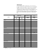
8-3 Reduced Voltage Starting Table 8.K Typical Voltage, Current and Torque Characteristics for NEMA Design B Motors Starting Method % Voltage at Motor Terminals Full Voltage Motor Starting Current as a % of: Line Current as a % of: Motor Starting Torque as a % of: Locked Rotor Current Full Load Current Locked Rotor Current Full Load Current Locked Rotor Torque Full Load Torque 100 100 600 100 600 100 180 Autotrans.
8-4 Reduced Voltage Starting Reduced Voltage (cont.) There are two methods of transition: Open Circuit Transition and Closed Circuit Transition. Open circuit transition means that th motor is actually disconnected from the line for a brief period of time when the transition takes place. With closed transition, the motor remains connected to the line during transition. Open circuit transition will produce a higher surge of current because the motor is momentarily disconnected from the line.
8-5 Reduced Voltage Starting The motor speed can determine the amount of current surge that occurs at transition. Transfer from reduced voltage to full voltage should occur at as close to full speed as possible. This also minimizes the amount of surge on the line. The following figures illustrate transition at low motor speed and near full speed. The transition at low speed shows the current surge as transition occurs at 550%, which is greater than the starting current o 400%.
8-6 Solid-state Reduced Voltage Starting The main function of solid-state controllers is their ability to provid a soft start or stepless reduced voltage start of AC motors. The same principles of current and torque apply to both electromechanical reduced voltage starters and solid-state controllers. Many solid-state controllers offer the choice of four starting modes: soft start, current limit start, dual ramp start, or full voltage start in the same device. Figure 8.
8-7 Reduced Voltage Starting Current limit starting can be used in situations where power line limitations or restrictions require a specific current load. The next illustration shows a 450% current limit curve. Other values may be selected, such as 200%, 300%, or 400%, depending on the particular application. Current limit starting is also used in applications wher higher starting torque is required compared to a soft start, which typically starts at less than 300% current.
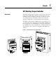
Chapter 9 Solid-state Starters Using SCRs Solid-state Starters Using SCRs In solid-state starters, silicon controlled rectifiers (SCRs) (se Figure 9.1) are used to control the voltage output to the motor. An SCR allows current to flow in one direction only. The amount of conduction of an SCR is controlled by the pulses received at the gate of the SCR. When two SCRs are connected back to back (se Figure 9.
9-2 Solid-state Starters Using SCRs Solid-state Starters Using SCRs (cont.) Figure 9.3 Different Firing Angles (Single-phase Simplification) Suppl Voltage Firing for Approx.
Chapter 10 Reference Introduction Certain mechanical parameters must be taken into consideration when applying motor controllers. The following section explains thes parameters and how to calculate or measure them. Motor Output Speed/Torque/Horsepower The speed at which an induction motor operates depends on the input power frequency and the number of poles for which the motor is wound. The higher the frequency, the faster the motor runs. The more poles the motor has, the slower it runs.
10-2 Reference Torque and Horsepower (cont.) Torque is merely a turning effort. In the previous illustration, it takes one pound at the end of the one foot wrench to turn the shaft at a steady rate. Therefore, the torque required is one pound × one foot, or one foot-lb. If the wrench were turned twice as fast, the torque required would remain the same, provided it is turned at a steady rate. Horsepower, on the other hand, takes into account how fast the shaft is turned.
10-3 Reference The following graph illustrates a typical speed-torque curve for a NEMA Design B induction motor. An understanding of several points on this curve will aid in properly applying motors. Figure 10.
10-4 Reference Torque and Horsepower (cont.) Full-load Torque (FLT) The full-load torque of a motor is the torque necessary to produce its rated horsepower at full-load speed. In foot-lbs, it is equal to the rated horsepower, multiplied by 5250, divided by the full-load speed in RPM. In addition to the relationship between speed and torque, the relationship of current draw to these two values is an important application consideration.
Reference 10-5 kVA per Horsepower is Calculated as Follows: For three-phase motors: 1.73 × Current (in Amperes) × Volts kVA/HP = ------------------------------------------------------------------------1,00 ×0H For single phase motors: Current (in Amperes) × Volts kVA/HP = ---------------------------------------------------------1,00 ×0H Table 10. ➊ NEMA Locked-Rotor Current Code Letters Letter Designation kVA per HP ① A 0–3.15 B 3.15–3.55 C 3.55–4.0 D 4.0–4.5 E 4.5–5.0 F 5.0–5.6 G 5.6–6.
10-6 Reference Torque and Horsepower (cont.) By manipulating the preceding equation for kVA/HP for three-phas motors, the following equation can be used for calculating lockedrotor current: 1,00 ×0H × kVA/HP LRA = -------------------------------------------1.73 × Volts This equation can then be used to determine the approximate starting current of any particular motor. For instance, the approximate starting current for 7-1/2HP, 230 volt motor with a locked-rotor kVA code letter of G would be: 1,00 ×07.
Reference Motor Output for NEMA Design Designations Polyphase 1–500 HP 10-7 NEMA has designated several specific types of motors, each having unique speed/torque relationships. These designs, along with some typical applications for each type, are described below. Following these descriptions are summaries of performance characteristics. Figure 10.
10-8 Reference Motor Output for NEMA Design Designations Polyphase 1–500 HP (cont.) Figure 10.6 Typical NEMA Design B Speed/Torque Curv Torque Speed Starting Current: Starting Torque: Breakdown Torque: Full-load Slip: Applications: Normal Normal Normal Normal Fans, blowers, pumps, machine tools, or other applications with normal starting torque requirements and an essentially constant load.
Reference 10-9 Figure 10.7 Typical NEMA Design C Speed/Torque Curve Torque Speed Starting Current: Starting Torque: Breakdown Torque: Full-load Slip: Applications: Low High Low Low The higher starting torque of NEMA Design C motors makes them advantageous for use on hard-to-start loads such as plunger pumps, conveyors, and compressors.
10-10 Reference Motor Output for NEMA Design Designations Polyphase 1–500 HP (cont.) Figure 10.8 Typical NEMA Design D Speed/Torque Curve Torque Speed Starting Current: Starting Torque: Breakdown Torque: Full-load Slip: Applications: Normal High None High (5-13%) The combination of high starting torque and high slip make NEMA Design D motors ideal for use on very high inertia loads and/or in applications where a considerable variation in load exists.
Reference 10-11 Table 10.M Motor Output - Comparison of NEMA Polyphase Designs NEMA Design Starting Torque Locked Rotor Torque Breakdown Torque % Slip Applications A High High High < 5% Broad applications including fans, blowers, pumps, and machine tools. B Normal Normal Normal < 5% Normal starting torque for fans, blowers, rotary pumps, unloaded compressors, conveyors, metal cutting, machine tools, miscellaneous machinery.
10-12 Reference Calculating Torque (Acceleration Torque Required for Rotating Motion) (cont.) The same formula can be used to determine the minimum acceleration time of a given drive, or it can be used to establish whether a drive can accomplish the desired change in speed within the required time period.
Reference 10-13 WK2 or WR2 Where: WR2 refers to the inertia of a rotating member that was calculated by assuming the weight of the object was concentrated around its rim at a distance R (radius) from the center (e.g., flywheel). WK2 refers to the inertia of a rotating member that was calculated by assuming the weight of the object was concentrated at some smaller radius, K (termed the radius of gyration). To determine the WK2 of a part, the weight is normally required (e.g., cylinder, pully, gear).
10-14 Reference AC Motor Formulas Freq × 12 Sync Speed = --------------------------------Number of Poles Where: Sync Speed = Synchronous Speed (RPM) Freq = Frequency (Hz) % Sli Sync Spee –dFL Spee = ------------------------------------------------ × 10 Sync Spee Where: FL Speed = Full Load Speed (RPM) Sync Speed = Synchronous Speed (RPM) 2 ( WK of Loa ) Reflected WK = -------------------------------------2 2 ( Reduction Rati ) Where: WK2 = Inertia (ft.-lb.
10-15 Reference Torque Characteristics on Common Applications This chart offers a quick guideline on the torque required to breakaway, start and run many common applications. Table 10.
10-16 Reference Torque Characteristics on Common Applications (cont.) Table 10.N (cont.
10-17 Reference Table 10.N (cont.
10-18 Reference Electrical Formulas (cont.) I×E kVA (1-phase) = ----------1,00 I × E × 1.73 kVA (3-phase = ------------------------1,00 Where: kVA = Kilovolt-Amperes I = Current (Amperes) E = EMF or Voltage (Volts) I × E × PF kW (1-phase) = --------------------1,00 I × E × PF × 1.42 kW (2-phase) = -----------------------------------1,00 I × E × PF × 1.
Reference Other Formulas Calculating Accelerating Force for Linear Motion: W × ∆V F (Acceleration) = ------------------1,93 ×3t Where: F = Force (lbs.) W = Weight (lb.) DV = Change in Velocity (FPM) t = Time to accelerate weight (seconds) Start kVA HP × ------------------ × 1,00 HP LRA = -----------------------------------------------------E × 1.73 Where: LRA = Locked Rotor Amperes HP = Horsepower kVA = Kilovolt-Amperes E = EMF or Voltage (Volts) 60 Hz LR LRA @ Freq.
10-20 Reference Engineering Constants (cont.) Weight 16 oz. = 1 lb. 2.2046 lb. = 1 kg. 2.309 ft. water at 6 ° F = 1 PSI 28.35 gm = 1 oz. 59.76 lbs. = Weight of 1 Cu. ft. of water at 21 ° F 0.062428 lb. per cu. ft. = 1 kg/cu. m 62.355 lbs = Weight of 1 cu. ft. water at 6° F 8 (8.32675) lbs. = Weight 1 gal. water at 62 ° F Power 1.3410 HP = 1 kW 2.545 BTU per hr. = 1 HP 33,000 ft.-lb. per min. = 1 HP 550 ft.-lb. per sec. = 1 HP 745.7 W = 1 HP Area 10.764 sq. ft. = 1 sq. m 1,273,239 circular mils = 1 sq.
Reference Volume 1,728 cu. in. = 1 cu. ft. 231 cu. in. = 1 gal. (U.S. 277.274 cu. in. = 1 gal. (British) 27 cu. ft. = 1 cu. yd. 31 gal. (31.5 U.S. gal.) = 1 barrel 35.314 cu. ft. = 1 cu. m 3.785 liters = 1 gal. 61.023 cu. in. = 1 liter 7.4805 gal. = 1 cu. ft. Temperature ° = degrees C = Celsius (Centigrade F = Fahrenheit BTU = British Thermal Unit Length yd. = yard m = meter mm = millimeter (1/1000 of a meter cm = centimeter ( 1/100 of a meter) in. = inch ft. = feet km = kilometer Weight oz. = ounce lb.
10-22 Reference Engineering Constants (cont.) Work/Inertia ft.-lb. = foot pounds WK2 = moment of inertia N-m2 = Newton meters2 Area sq. ft. = square feet sq. m = square meters mil = unit of length or angular measurement mm2 = square millimeters sq. in. = square inch Rotation/Rate FPM = feet per minute FPS = feet per second m/s = meters per second mph = miles per hour cfm = cubic feet per minute Mathematic p = “pi” rad. = radians p = Density E = Summation D = Chang Pressure kg. per sq.
10-23 Reference Conversion Factors Table 10.O Length To Convert: To: Multiply by: Meters Feet 3.281 Meters Inches 39.37 Inches Meters .0254 Feet Meters .3048 Millimeters Inches .0394 Inches Millimeters 25.4 Threads/Inch Millimeter Pitch Divide into 25.4 Yards Meters 0.914 Example: 10 Meters x 3.281 = 32.81 Feet Table 10.P Area To Convert: To: Multiply by: Circular mil Meter2 0.50 x 10⁻⁹ Yard2 Meter2 0.8361 Example: (0.5 x 10⁻⁷ Circular mils = .00000005 m 2) Table 10.
10-24 Reference Conversion Factors (cont.) Table 10.R Rotational/Rate To Convert: To: Multiply by: RPM deg./sec. 6.00 RPM Rad./sec. 0.1047 deg./sec. RPM 0.1667 Rad./sec. RPM 9.549 FPM m/s .00508 FPS m/s 0.3048 gal./min. cm3/sec. 63.09 in./sec. m/sec. .0254 km/hr m/sec. 0.2778 mph m/sec. 0.447 mph km/hr 1.609 yd. 3/min. m3/sec. 0.1274 Example: 1800 RPM x 6.00 = 10800 deg./sec. Table 10.S Moment of Inertia To Convert: To: Multiply by: Newton-Meters2 ft.-lb.2 2.
10-25 Reference Table 10.U Torque To Convert: To: Multiply by: Newton-Meters ft.-lb. 0.7376 ft.-lb. Newton-Meters 1.3558 ft.-lb. ft.-lb. .0833 ft.-lb. ft.-lb. 12.00 Example: 30 Newton-Meters x 0.7376 = 22.13 lb-ft. Table 10.V Volume To Convert: To: Multiply by: cm3 m3 .000001 fl. oz. cm3 29.57 ft.3 of water (39. ° F) kg (or liter) 28.32 cfm m3/sec. .000472 liter m3 .001 yd.3 m3 0.7646 Example: 250 cm 3 x .000001 = .00025 m 3 Table 10.
Glossary AC Alternating current. AC Contacto An alternating current (AC) contactor is designed for the specific purpose of establishing or interrupting an AC power circuit. Alphanumeric Display A device capable of displaying characters (letters, numbers, and symbols) but not graphics. Ambient Temperature Ambient temperature is the temperature of air, water, or a surrounding medium where equipment is operated or stored.
Glossary-2 • Dynamic Braking (DC Drives) – Slows the motor by applying a resistive load across the armature leads after disconnection from the DC supply. This must be done while the motor field is energized. The motor then acts as a generator until the energy of the rotating armature is dissipated. This is not a holding brake. • Motor Mounted or Separately Mounted Brake is a positive action, mechanical, friction device. Normal configuration is such that when the power is removed, the brake is set.
Glossary-3 Constant Horsepower Range A range of motor operation where motor speed is controlled by field weakening. Motor torque decreases as speed increases. Since horsepower is speed multiplied by torque (divided by a constant), the value of horsepower developed by the motor in this range is constant. Constant Torque Range A speed range in which the motor is capable of delivering a constant torque, subject to cooling limitations of the motor.
Glossary-4 Disable To inhibit logic from being activated. Display That image that appears on a CRT screen or on other image projection systems. Display Menu The list of displays from which you select specific information for viewing. Duty Cycle The relationship between the operating and rest times or repeatable operation at different loads. Dynamic Braking See Braking. Efficienc Ratio of mechanical output to electrical input indicated by a percentage.
Glossary-5 • NEMA Type 9 – An enclosure designed for a hazardous location, Class 2 Groups F and G per the National Electrical Code. The atmosphere in which this control must operate will contain carbon black, coal or coke dust, flour, starch, or grain dust. • NEMA Type 12 – Designed for industrial use. The enclosure is intended fo use in applications where it is desirable to exclude such materials as cooling oil, seepage, dust, lint, fibers and filings.
Glossary-6 Frequency The number of periodic cycles per unit of time. Front of a Motor The end opposite the coupling or driving pulley (NEMA). This is sometimes called the opposite pulley end (O.P.E.) or commutator end (C.E.). Full-load Torque The full-load torque of a motor is the torque necessary to produce rated horsepower at full-load speed. Gate The control element of an SCR (silicon controlled rectifier) commonly referred to as a thyristor.
Glossary-7 International Standards Organization (ISO) An organization established to promote development of international standards. Isolation Transformer A transformer that electrically separates the drive from the AC power line. An isolation transformer provides the following advantages: 1. In DC motor applications, it guards against inadvertent grounding of plant power lines through grounds in the DC motor armature circuit. 2. Enhances protection of semiconductors from line voltage transients. 3.
Glossary-8 Logic General term for digital circuits and programmed instructions to perform required decision-making and computational functions. M 1. Mega. A prefix used with units of measurement to designate a multiple of 1,000,000. 2. 1M = 220 = 1,048,576. A prefix used as a multiple for bits, bytes, or words in denoting size of a block of data or memory. Example: 2M bytes = 2,097,152 bytes. Megger Test A test used to measure an insulation system’s resistance.
Glossary-9 NEC The National Electrical Code are recommendations of the National Fire Protection Association and is revised every three years. City or state regulations may diffe from code regulations and take precedence over NEC rules. NEMA The National Electrical Manufacturers Association is a non-profit organization organized and supported by manufacturers of electrical equipment and supplies.
Glossary-10 • Guarded Machine – (NEMA Standard) is an open machine in which all openings giving direct access to live metal or rotating parts (except smooth rotating surfaces) are limited in size by the structural parts or by the screens, baffles, grills, expanded metal or other means to prevent accidental contact with hazardous parts. Openings giving direct access to such live or rotating parts shall not permit the passage of a cylindrical rod 0.75 inch in diameter.
Glossary-11 PLC ® Controller 1. An Allen-Bradley programmable controller. 2. An Allen-Bradley programmable controller with a name that includes th letters PLC. Se Programmable Controller. Plugging Plugging refers to a type of motor braking provided by reversing either line voltage polarity or phase sequence so that the motor develops a counter-torque which exerts a retarding force to brake the motor.
Glossary-12 RS-485 An EIA standard that specifies electrical characteristics of balanced-voltage digital interface circuits in a multi-point link. SCR Silicon Controlled Rectifier. A solid-state uni-directional latching switch. Scrolling The vertical movement of data on a display screen caused by the dropping of one line of displayed data for each new line added at the opposite end.
Glossary-13 Star Connection 1. The arrangement of phase windings, in a polyphase circuit, in which one end of each phase winding is connected to a common junction. In a three-phase circuit, it is sometimes called a Y connection. 2. Contrasted with Delta Connection. Status The condition at a particular time of any numerous entities within a system. These conditions may be represented by values in a status line.
Glossary-14 • Dust-ignition-proof Machine – is a totally enclosed machine whos enclosure is designed and constructed in a manner which will exclude ignitabl amounts of dust or amounts which might affect performance or rating, and which will not permit arcs, sparks or heat otherwise generated or liberated inside of the enclosure to cause ignition or exterior accumulations or atmospheric suspensions of a specific dust on or in the vicinity of the enclosure.
Publication 0150-5.2 - September 1998 Supersedes Publications 150-5.1 - November 1994 and 150-5.2 - June 1995 1998 Rockwell International. All Rights Reserved.