
Owner manual
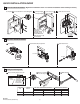
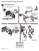
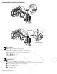
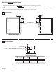
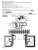
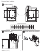
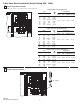
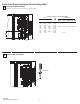
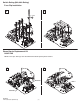

Table of Contents Page
Quick Installation Guide 2
-
Disconnect Switch Installation
- Disconnect Handle Installation
- Cutting Connecting Rod
Quick Installation Guide (continued) 3
-
Connecting Rod Installation
Connecting Rod Adjustment Procedure 4
Enclosure Without Handle Cutout 5
- Locate Handle
- Drill Handle Holes
Door Catch Mounting Bracket Installation 6
Disconnect Switch Installation 7
-
Locate Disconnect Switch
- Install Disconnect Switch
- Assemble and Install Line Terminal Guard
Trailer Fuse Block Installation (30A, 60A, 100A) 8
Trailer Fuse Block Installation (200A) 9
Fuse Clip Installation and Phase Barrier Replacement (30A, 60A) 10
Fuse Clip Installation and Phase Barrier Replacement (100A) 11
Fuse Clip Installation (200A)
12
Fuse Clip Installation (Switch Rating 200A) for 400A Class J Fuses 13
Phase Barrier Replacement (200A) 14
Bulletin 1494V Disconnect Switch Kit 15
Bulletin 1494V Disconnect Switch Kit Optional Accessory List 16
The following procedures are critical to the proper operation of the disconnect handle and switch.
Failure to follow these steps can result in damage to the equipment and/or serious injury or death to the
operator.
To prevent electrical shock, disconnect from power source before installing or servicing. Follow
NFPA 70E requirements. Install in suitable enclosure. Keep free from contaminants.
Bulletin 1494V Variable Depth Disconnect Switch Installation Instructions
(Cat 1494V-DS30; -DSX30 - Series D; 1494V-DS60; -DSX60 - Series D)
(Cat 1494V-DS100; -DSX100 - Series D; 1494V-DS200; -DSX200 - Series D)
WARNING
WARNING
PN-47400
DIR 10000056505 (Version 00)
Printed in U.S.A.