
User Manual
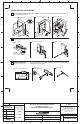
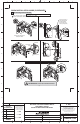
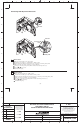
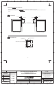
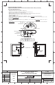
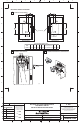
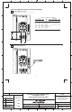
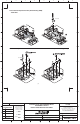
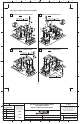

Table of Contents Page
Quick Installation Guide 2
-
Disconnect Switch Installation
- Disconnect Handle Installation
- Cutting Connecting Rod
Quick Installation Guide (continued) 3
-
Connecting Rod Installation
Connecting Rod Adjustment Procedure 4
Enclosure Without Handle Cutout 5
-
Locate Handle
- Drill Handle Holes
Door Catch Mounting Bracket Installation 6
Disconnect Switch Installation 7
-
Locate Disconnect Switch
- Install Disconnect Switch
- Assemble and Install Line Terminal Guard
Trailer Fuse Block Installation 8
Phase Barrier Replacement and Terminal Adapter Installation 9
Fuse Clip Installation 10
Bulletin 1494V Disconnect Switch Kit 11
Bulletin 1494V Disconnect Switch Kit Optional Accessory List 12
ATTENTION: The following procedures are critical to the proper operation of the disconnect handle and switch.
Failure to follow these steps can result in damage to the equipment and/or serious injury or death to the operator.
BULLETIN 1494V 400A VARIABLE DEPTH
DISCONNECT SWITCH
INSTALLATION INSTRUCTION SHEET
1 1023056
1030857
42052-154
OF
N/A
N/A
N/A
REVISION
AUTHORIZATION
DR.
CHKD.
APPD.
DATE
DATE
DATE
E - DOC
LOCATION: MILWAUKEE, WISCONSIN U.S.A.
B-vertical.ai
DWG.
SIZE
SHEET
B
1234 56 78
A
B
C
D
E
F
G
H
REFERENCE
DIMENSIONS APPLY BEFORE
SURFACE TREATMENT
(DIMENSIONS IN INCHES)
TOLERANCES UNLESS
OTHERWISE SPECIFIED
.XX:
.XXX:
ANGLES:
42052
G. Ushakow 12-03-07
12-03-07
12-03-07
M. Jutz
J. Koziczkowski
ATTENTION: To prevent electrical shock, disconnect from power source before installing or servicing. Follow
NFPA 70E requirements. Install in suitable enclosure. Keep free from contaminants.
Bulletin 1494V Variable Depth Disconnect Switch Installation Instructions
(Cat 1494V-DS400; -DSX400 - Series D)
THIS DRAWING IS THE PROPERTY OF
ROCKWELL AUTOMATION, INC.
OR ITS SUBSIDIARIES AND MAY NOT BE COPIED,
USED OR DISCLOSED FOR ANY PURPOSE
EXCEPT AS AUTHORIZED IN WRITING BY
ROCKWELL AUTOMATION, INC.
113
2