
Installation Instructions (30A, 60A, 100A) Owner manual

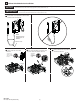
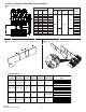

Handle Installation
1
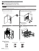
Rod Operated Switch Installation
1 Install gasket. 2 Install spring bracket and handle.
30 - 40 lb-in
Spring
Bracket
3 Install defeater lever.
7 - 11 lb-in
Defeater
Lever
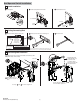
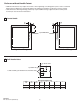
Cutting Connecting Rod
2
1 Measure working depth of enclosure. 2 Measure, mark and cut connecting rod. 3 Remove burrs.
N
Enclosure
Working Depth
(Inside Flange
of Enclosure to
Mounting Plate)
Mounting
Plate
N minus 3"
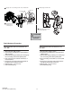
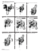
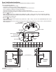
Connecting Rod Installation
3
1 Verify that disconnect switch and handle are in “OFF” position
(Switch blades will be visible).
Drive Bar
2
Rotate connecting rod
into drive bar (11) full
turns.
2
6-1/2”
30A - 60A - 100A Disconnect Switches
Enclosure Working Depth “N”
Min.
19”
Max.
1494U-R1
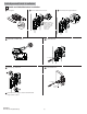
Connecting Rod
Align threaded rod
toward handle and,
if needed, rotate
counterclockwise
until ears engage the
primary link slots.
3
4
For enclosures with a working depth greater than 19”
but less than 23”, use connecting rod kit 1494V-RA4.
PN-224754
DIR 10001182729 (Version 01)
See steps and for final rod alignment.
2
3
2
4
Ensure that the handle is
in the full “OFF” position.
(3)