
Instructions
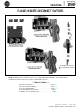
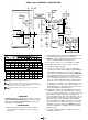

DOOR AND HARDWARE CONSTRUCTION
Large Enclosures
Cat. Nos. 1494F-L4 and
2-Holes
# IO-32 Tap
tn
/AXMin.
i
Nominal
#G
IL1
IAWMin.
Clearance Holes
for
2-#1/4-20
a
Screws
il
I
BE
Min.
I
No. BD BE
1494F-L1
*
LL1
-
1494F
LL2
5
-
iii
‘1
I
--d-------------
41
-------------
2. Select the dimensions from above which apply to the
roller latching arrangement to be installed.
NOTE: Door catch supplied with all disconnects is not
to be used with these door hardware kits.
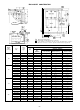
3. Locate holes in door to secure handle assembly.
4. Determine Dimensions “BA” and “AV” to locate
locking bar guide bracket(s).
5. Locate door catch using “P” and “T” dimensions.
Location varies with each hardware kit. On 1494F-L4
and 1494F-LL4 hardware kits, attach the adjustable
catch after the support bracket is located. NOTE: Door
catch and guide bracket(s) are made with projections
for welding to the enclosure door. However, if a
specific installation permits, holes can be drilled in
the door catch and guide bracket(s) using the projec-
tions as centers. Then, after proper location and
using them as templates, corresponding holes can
be drilled in the enclosure door. Door catch and
guide bracket(s) are then fastened to the enclosure
door with hardware furnished by user.
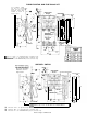
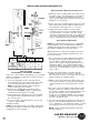
6. Establish the length of the top locking bar by measur-
ing Dimension “AX” and subtracting
3
/4" for Kits L1,
LL1, L2, and LL2; subtract
1
1
/
8" for Kits L4 and LL4.
Determine the length of the bottom locking bar by
measuring Dimension “BE” and subtracting 3/4" for
Kits L2 and LL2; subtract 1
1
/8" for Kits L4 and LL4.
Dimension “BC” is determined by measuring Di-
mension
"AW"
and adding 3
1
/2" for Kits L1, LL1, L2,
and LL2; add 3%” for Kits L4 and LL4. Locate, drill,
and tap holes where necessary. NOTE: These stan-
dard mill rectangular locking bars are not supplied
with these kits.
7. The door locking hardware assembly can now be
attached to the door.
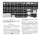
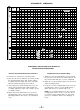
Dimensions In Inches
I
Amps)
P T AV 1 AW 1 AX
0
1 AY 1 AZ 1 BA 1
BB
I I I
SMALL & INTERMEDIATE ENCLOSURES q
30 2
5
/32 2
1
/8 3
1
/16 3 13
1
/2
1
/4
3
/8 3
7
/8
60 2
5
/32 2
1
/8 3
1
/16
3 14
1
/2
1
/4
3
/8
3
7
/8
100 2
5
/32 2
1
/8 3
1
/16 3
18
7
/8
1
/2
1
/4
3
/8 3
7
/8
200 2
5
/16
2
1
/
8
1
/8 3
1
/16
3
23
25
/32
1
/2
1
/4
3
/8 3
15
/16
LARGE ENCLOSURES
Im
30 2
1
/4 1
9
/16
3
11
/16
3
1
/8
13
1
/8
5
/8
5
/16
1
/2
4
60
2
1
/4
1
9
/16
3
11
/16
3
1
/8 13
5
/8
5
/8
5
/16
1
/2
4
100 2
1
/4 1
9
/16 3
11
/16
3
1
/8
18
1
/2
5
/8
5
/16
1
/2
4
200
2
11
/32
19
/16 3
11
/
16 3
1
/8 23
13
/32
5
/8
5
/16
1
/2
4
aWhen
using the minimum wiring space for the maximum size wire
as shown on Page 2 Dimensions
"S"
and "Y"
muse with Hardware Kits 1494F-L1 and LL1 (top and side latching);
1494F-L2 and 1494F-LL2 (top and bottom latching); and 1494F-L3
(side latching accessory for 1494F-L2 and
LL2).
muse with Hardware Kits 1494F-L4 and LL4 (top, side and bottom
latching).
GUIDELINES
Small Enclosures: 30” high or less with 2 or 3 point
latching. Intermediate Enclosures: 30” thru 48” high
with 3 point latching. Large Enclosures: Above 48”
high with 3 point latching.
INSTRUCTIONS
1. Check all minimum enclosure and door dimen-
sions required for installation. Refer to Pages 2, 3
and above.
-
6-