
Instructions
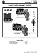
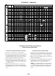

FUSIBLE SWITCH AND FUSE BLOCK KIT
Door hardware locking
bar must not extend
below this line above
disconnect switch when
installed as shown on
Pages 6 and 7.
-l
A
f
AT
1
t-l
J
4
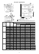
Flange Plate
AB
2- Mtg. Holes
f
or 200 Amp.
only
Terminal Hardware
-7
1
AL
.
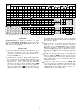
HDimension “AK” is for right-hand flange construction only.
aDimension "AK," is for left-hand flange construction only.
qDimension “Z” is for ALLEN-BRADLEY pressure connectors only.
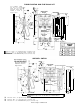
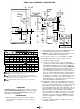
UNFUSED SWITCH
below this line above
disconnect switch when
installed as shown on
Pages 6 and 7.
Terminal Hardware
Flange Plate
AB
CAUTION
-
Spring Guide extends beyond this line on 100 and
200A switches only. 113/16" on
100A
and 7/16" on 200A switches. 1
q Dimension “AK” is for right-hand flange construction only.
q Dimension
"AK,"
is for left-hand flange construction only.
q Dimension “Z” is for ALLEN-BRADLEY pressure connectors only.
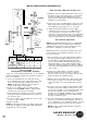
Refer to Page 5 for Dimensions