
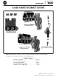
Instructions
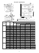
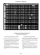

NEMA
Size
Dimensions In Inches
(Amps)
C D E F G H J K L M N P R
Sm
T
U MIN. Mix. V
M\.
Mk
X Y q
WITHOUT DOOR HARDWARE
30
1
3
/
8 1
3
/16 2
1
/4 1
7
/16
5
/8 8
1
/2 1 1
1
/16
15
/32/ 7
3
/16
9
/32
1
/4 2
1
/8
4
31
/32
2
1
/16 2
9
/16
1
1
/16 1
3
/8
7
/8
1
/4
9
/16 4
5
/16 1
1
/2
60
6
3
/8 1
3
/16 2
1
/4 1
7
/16
5
/8 8
1
/2 1
1
/16
15
/32 7
3
/16
9
/32
7
/32 2
1
/8 4
31
/32 3
1
/4 2
9
/
16 1
1
/16 1
3
/8
7
/8
1
/4 1
7
/8 4
5
/16 2
100 8
1
/2 1
3
/16 2
1
/4 1
7
/16
5
/8 8
1
/2 2
15
/16
15
/32 7
3
/16
9
/32
3
/8 2
1
/8 7
1
/64 8
9
/6
4
2
9
/16 1
1
/16 1
3
/8
7
/8
1
/4 3
21
/64 4
11
/16 5
200 91
1
/4 2
3
/8
1
11
/16
11
/16 1
11
/8 2
15
/16
13
/16 9
1
/2
11
/32
33
/64
2
9
/32 7
1
/16
1
0
13
/32 2
1
/2 1
1
/8 1
3
/8
7
/8
1
/4 4
1
/32 6
3
/4 7
SMALL & INTERMEDIATE ENCLOSURES WITH DOOR HARDWARE
30 6
3
/8 1
3
/16 2
9
/16 1
7
/16
5
/8
8
1
/2 1
1
/16
60
6
3
/8
1
3
/1
6
2
9
/16 1
7
/16
5
/8
8
1
/2 1
1
/16
100 8
1
/2
1
3
/16 2
9
/16 1
7
/16
5
/8 8
1
/2 2
15
/16
200 9 1
1
/4 2
5
/8 1
11
/16
11
/16 11
1
/8 2
15
/16
5
/8 1
8
1
/2 1 1
1
/16
15
/32 7
3
/16
9
/32
1
/4 2
5
/32 4
31
/32 2
1
/4 2
1
/8
15
/32 7
3
/16
9
/32
7
/32 2
5
/32
4
31
/32 3
1
/4 2
1
/8
15
/32 7
3
/16
9
/32
3
/8 2
5
/32 7
1
/64 8
9
/64 2
1
/8
13
/16 9
1
/2
11
/32
33
/64 2
5
/16 7
1
/16
10
/32 2
1
/8
LARGE ENCLOSURES WITH DOOR HARDWARE
15
/32 7
3
/16
9
/32
1
/4 2
1
/4 4
31
/32 2
3
/4 1
9
/16
15
/32 7
3
/16
9
/32
7
/32 2
1
/4
4
31
/32 3
1
/4 1
9
/16
15
/32 7
3
/16
9
/32
3
/8 2
1
/4 7
1
/64 8
9
/64 1
9
/16
13
/16 9
1
/2
11
/32
33
/64 2
11
/32 7
1
/16 10
13
/32 1
9
/16
q
Minimum wiring space for the maximum wire size.
GUIDELINES
Small Enclosures: 30” high or less with 2 or 3 point
latching. Intermediate Enclosures: 30” thru 48” high
with 3 point latching. Large Enclosures: Above 48”
high with 3 point latching.
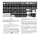
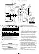
INSTRUCTIONS
1. Select the dimension table(s) which applies to your
enclosure construction, door and door hardware
construction and/or disconnect type (fusible or un-
fused) and NEMA size.
2. Determine the enclosure flange width (Dimension
E), the disconnect mounting depth (Dimension C),
the enclosure’s length (Dimension B) and width
(Dimension A + D) to insure that the fabricated
enclosure is as large as these minimum values. NOTE:
The enclosure length is based upon the minimum
wire space (Dimension Yip) at top and bottom re-
quired by N.E.C. The minimum enclosure opening
+
1
1
/8
1
1
/8
1
1
/8
and depth will insure adequate space for mounting
the disconnect inside the enclosure and securing it to
the enclosure flange.
Refer to N.E.C. for required wire bending space
(Dimension “Y”). If wire or pressure connectors
other than those of ALLEN-BRADLEY are used, this
dimension should be adjusted accordingly. Values
specified for
“Y”
will provide “S” distance as shown.
Any change in
“Y”
will cause an identical change in
“S”.
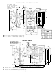
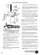
Provide slot and mounting holes on the right-hand
flange as indicated. NOTE: Location of holes in enclo-
sure mounting plate for disconnect switch and fuse
block adapter plate can be determined from line
drawings on Page 4.
Locate door catch using “P” and “T”. NOTE: With
enclosures using door hardware, disregard the door
catch supplied with disconnect and use door catch
furnished with door hardware. Refer to Page 6 for
additional door catch instructions.
-3-