
Software Manual


Initial Setup
3-5
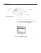
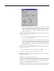
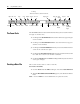
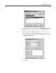
2. Verify that the plotter DIP switches are set as shown below. The
switches are located on the bottom of the plotter.
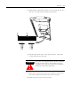
3. Plug the appropriate power cord into the plotter. The plotter
accepts 100/240V AC, 50/60 Hz.
4. Attach blue composite base plate to the plotter by placing the 2
pins on the plotter bed into the holes in the base plate.
5. Install pen in the top slot of the carousel.
Switch Bank 1 Switch Bank 2
12345678
ON
12345678
ON
DIP Switches
1 OFF
2 OFF
3 OFF
4 OFF
5 OFF
6 ON
7 ON
8 ON
1 ON
2 ON
3 OFF
4 OFF
5 OFF
6 OFF
7 OFF
8 OFF
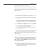
ATTENTION
!
The power cord supplied with the plotter is shielded.
Do not use other power cords. Failure to use the
supplied power cord may result in electromagnetic
interference with other equipment.