WinABMS Marking System Software Cat. Nos.
Important User Information Because of the variety of uses for the products described in this publication, those responsible for the application and use of this control equipment must satisfy themselves thatall necessary steps have been taken to assurethat each applicationandusemeetsallperformanceandsafetyrequirements,including any applicable laws, regulations, codes and standards. Theillustrations,charts,sampleprogramsandlayoutexamplesshowninthis guide are intended solely for purposes of example.
European Communities (EC) Directive Compliance If this product has the CE mark it is approved for installation within the European Union and EEA regions. It has been designed and tested to meet the following directives.
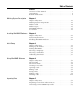
Table of Contents Preface Overview of this Manual . . . . . . . . . . . . . . . . . . . . . . . . . . . . . i Conventions . . . . . . . . . . . . . . . . . . . . . . . . . . . . . . . . . . . . . ii Related Publications . . . . . . . . . . . . . . . . . . . . . . . . . . . . . . . ii Marking System Description Chapter 1 Chapter Objectives . . . . . . . . Marking System Components. Marker Cards . . . . . . . . . . . . Marker Types . . . . . . . . . . . . WinABMS Software . . . . . . . . Accessories . . . .
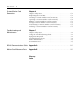
Table of Contents ii Custom Marker Card Geometries Chapter 6 Troubleshooting and Maintainance Chapter 7 RS-232 Communications Cable Appendix A . . . . . . . . . . . . . . . . . . . . . . . . . . . . . . . . . . . . . . . . . . . . A-1 Marker Card Reference Data Appendix B . . . . . . . . . . . . . . . . . . . . . . . . . . . . . . . . . . . . . . . . . . . . B-1 Chapter Objectives . . . . . . . . . . . . . . . . . . . . . Explaining the Tool Bar. . . . . . . . . . . . . . . . . .
Preface Overview of this Manual Thismanualdescribes howtousecomponentsoftheAllen–BradleyMarking SystemSoftwaretocreateandprintmarkersforBulletin1492TerminalBlocks and accessories. The following table describes the contents of this manual. Chapter i Title Contents Preface Provides an overview of the manual. 1 Marking System Description Provides a brief overview of the hardware and software. Includes a description of system accessories.
Preface ii Intended Audience BasicknowledgeoftheMicrosoftWindows™OperatingSystemisrequiredto operate the Allen–Bradley Marking System Software. Conventions This manual uses the following conventions: • Allen–Bradley Marking System software is referred to as WinABMS. • Marker refers to the individual tabs that snap onto a terminal block. Terminal Block Marker • A marker card is a set of 100 markers. For Catalog No. 1492-SMN83, a marker card is a set of 50 markers.
Chapter 1 Marking System Description Chapter Objectives This chapter describes: • Marking System components • Marker Cards • Marker types • Allen–Bradley Marking System (WinABMS) Software • Accessories Marking System Components There are two kits that WinABMS functions with: • 1492-PLTKIT Complete plotter kit • 1492-WPLTUP Update kit The Terminal Block Marking System kit (Catalog No.
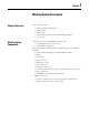
1-2 Marking System Description Personal Computer Marker Card (See Tables 1.A, 1.B) WinABMS Software Spacer Base Plate Plotter The Terminal Block Marking System Update Package (Catalog No. 1492-WPLTUP) includes: • Allen–Bradley Marking System (WinABMS) Software • Base Plate • IEC Spacers (6) • NEMA Spacers (6) • 5x5 Spacers (6) • Disposable Pens (4) • WinABMS User Manual (this document) In addition, you need: • Personal computer (see page 2-1 for system requirements) • Plotter Kit ( Catalog No.
Marking System Description 1-3 Plotting starts here Plotting starts here TB TB2 TB1 GND Vertical Direction (Layout 1) GND TB1 TB2 TB Horizontal Direction (Layout 2) Plotting always starts in the upper left corner of the marker card when you are holding it so that the marking is readable. This results in a different starting point for vertical (Layout 1) and horizontal (Layout 2) plotting. The plotter base plate has spaces for 6 marker cards.
1-4 Marking System Description Marker Types The marking system supports a variety of marker types. Table 1.A Allen–Bradley Markers Marker/Label Catalog No. Spacer Part No. Use With These Allen-Bradley Terminal Blocks and Accessories 1492–SM5X5 42165-188-53 1492-WM3, 1492-WMD1, 1492-CP4, Point I/O 1492–SM5X9 42165-188-52 1492-WR3, 1492-WD3, 1492-W3TW, 1492-WKD3..., 1492-WTC3..., 1492-WTF3..., 1492-WTS3..., 1492-R3, 1492-R3T, 1492-R3Q, 1492-RC3, 1492-RKD3, 1492-RTS2, 1492-RTSG2, 1492-RG3, 1492-RD3.
Marking System Description 1-5 Table 1.A Allen–Bradley Markers Marker/Label Catalog No. Spacer Part No. Use With These Allen-Bradley Terminal Blocks and Accessories 1492-MR9 N/A 1492-R3..., 1492-R4..., 1492-R6..., 1492-R10, 1492-R16, 1492-R4P, 1492-RC3, 1492-RD3..., 1492-RD4, 1492-RKD3, 1492-RTS2…, 1492-RTSG2,1492-RG3, 1492-RG3T, 1492-RG3Q, 1492-RG4, 1492-RG4T, 1492-RG4Q, 1492-RG6, 1492-RG6T, 1492-RG10, 1492-RG16, 1492-RFB4…, 1492-RAFB4…, 1492-RTF2, 1492-R2T 1492-MR15 N/A 1492-R3...➊, 1492-R4...
1-6 Marking System Description Table 1.B Additional Markers Supported Accessory Plate Marker Type Entrelec RC55, RC510, RC65, RC610 (67 x 110mm only), RC810 Phoenix ZB5, ZB6, ZB8, ZB10, ZBM5, ZBM6 Wieland Marker Sizes (mm): 5 x 8.3, 6 x 8.3, 5 x 14, 6 x 14, 8 x 8.3 Wago WSB 209-501, 209-701, 248-501 Weidmüller DEK 5/5 MC, 5/6 MC, 5/6.5 MC WS8/5 MC, WS10/5 MC, WS12/5 MC, WS12/6 MC, WS12/6.
Marking System Description 1-7 Accessories Table 1.C Accessories Item Catalog No.
Chapter 2 Installing WinABMS Software Chapter Objectives This chapter covers: • System requirements • Installation of WinABMS Software System Requirements The following is a list of recommended hardware and software needed to install and run the WinABMS software: • Personal computer using 80486 or higher processor • Microsoft Windows version 95 or later and NT or later. • 8 MB hard disk space • CD drive or internet access.
2-2 Installing WinABMS Software 3. Select “Download WinABMS software.” Note: You may be prompted to register prior to downloading the software. 4. Select “Download.” Note: You will be prompted for the download directory. 5. Run ABMSINST.EXE Note: Installation program will prompt you for the default language and the installation directory. 6. Installtion is now complete.
Chapter 3 Initial Setup Chapter Objectives This chapter shows how to: • Set up the Plotter • Cat. No. 1492–WPLTKIT • Cat. No. 1492–PLTKIT • Start WinABMS • Select a language • Select a COM Port • Calibrate the Plotter Setting Up the Plotter To setup the Cat. No. 1492-WPLTKIT plotter: Note: If your system is already set up and running ABMS (DOS) software, go to section on Selecting a COM Port. 1. Use the communications cable (provided with Catalog No.
3-2 Initial Setup RS-232 Serial Communication Port DIP Switches Power Switch Power Cord Connector 2. Verify that the plotter DIP switches are set as shown below. The switches that must be on (up position) are indicated by a red mark on the end.
Initial Setup ON 1 2 3 4 5 6 7 8 9 10 3-3 ON 1 2 3 4 Install pen in the top slot of the carousel. DIP Switches 10-Position Switch 4-Position Switch 1 ON 1 ON 2 ON 2 ON 3 OFF 3 ON 4 OFF 4 ON 5 ON 6 ON 7 ON 8 OFF 9 OFF 10 OFF 3. Plug the power cord into the plotter. The plotter accepts 100/ 120V AC, 50/60 Hz.
3-4 Initial Setup ATTENTION ! The power cord supplied with the plotter is shielded. Do not use other power cords. Failure to use the supplied power cord may result in electromagnetic interference with other equipment. 4. Replace aluminium base plate and holders with the blue composite base plate. Attach blue composite base plate to the plotter by inserting the 2 locating pins into the holes in the plotter bed. 5. Install pen in the top slot of the carousel. To setup the Cat. No. 1492-PLTKIT plotter: 1.
Initial Setup 3-5 2. Verify that the plotter DIP switches are set as shown below. The switches are located on the bottom of the plotter. ON ON 1 2 3 4 5 6 7 8 1 2 3 4 5 6 7 8 DIP Switches Switch Bank 1 1 2 3 4 5 6 7 8 OFF OFF OFF OFF OFF ON ON ON Switch Bank 2 1 2 3 4 5 6 7 8 ON ON OFF OFF OFF OFF OFF OFF 3. Plug the appropriate power cord into the plotter. The plotter accepts 100/240V AC, 50/60 Hz. ATTENTION ! The power cord supplied with the plotter is shielded. Do not use other power cords.
3-6 Starting WinABMS Starting WinABMS To start WinABMS: 1. Locate the WinABMS icon and double click. Selecting a Language You can run the software in one of five languages: • English • French • German • Italian • Spanish The default language is English. To change the language: 1. Click on Language under the Options heading. 2. Then click on the language you desire. Selecting a COM Port This section shows how to select a computer COM port for communicating with the plotter.
Starting WinABMS 3-7 . Calibrating the Plotter Use the calibrate plotter function to align the marking pen with the marker cards. If the pen calibration is not set correctly, the printed text will not be positioned correctly on the marker card. Note: These procedures assume that the communications cable between the plotter and computer is connected, all communication settings have been made, and that the pen has been installed. To calibrate the plotter: 1. Slide a Spacer (Part No.
3-8 Starting WinABMS 2. Click on Plotter under the Options heading, then click on Calibrate. 3. When the Base Plate Calibration Menu appears, select the appropriate base plate and click on Calibrate. Note: Click on Calibrate, not on OK. 4. When the Calibrate Origin Menu appears, click on Point 1 to set the first calibration point.
Starting WinABMS 3-9 5. Click the movement arrows to move the pen until it is over the “crosshair” located in the upper left area of the base plate. Use your finger to lightly press the pen down. When the pen tip drops into the pin hole located in the “crosshair”, then the first point has been calibrated correctly. Note: Clicking on one of the Step Size boxes will allow you to move the pen in smaller increments. 6.
3-10 Starting WinABMS jarred and this power down and up will re-zero the plotter. If calibration is still off, repeat the entire calibration process.
Starting WinABMS 3-11 To Manually Adjust the Plotter Calibration Note: Manual adjustment should only be made if plotting is consistently shifted in the same direction for all 6 base plate locations. If, for example, plotting is high in position 1 but low in position 2, manual adjustment will not help. In this case the plotter bed, or the base plate, is out of tolerance, and must be corrected. 1. Make a test plot from positions 1, 2, 5, and 6.
Chapter 4 Using WinABMS Software Chapter Objectives This chapter describes how to use WinABMS Software: • Explaining the Tool Bar • Using the Zoom Tool • Creating a New File • Opening a File • Editing a File • Saving a File • Plotting a File • Deleting a File The Tool Bar The WinABMS software has a Tool Bar that can be used as shortcuts for the following commands.
4-2 Using WinABMS Software • Help The Tool Bar is shown below. Open a file Plot Create a new file Undo Replace Zoom In Zoom 1:1 Copy Save a file Cut The Zoom Tools Paste Zoom Out Zoom All Align Center Font Align Top Align Bottom Align Left Align Right Align Middle Layout 2 Help Layout 1 Display Symbol Bar Toggle The WinABMS software has Zoom Tools that allow you to view the markers in larger or smaller sizes. 1.
Using WinABMS Software 4-3 3. Click on one of the marker areas then click on Marker Card under the Format heading or double click on one of the marker areas. 4. When the Markercard Info Menu appears, enter a name for the markercard (optional), add the order information (optional), select a layout style (style 1 is vertical, and style 2 is horizontal), and select a geometry from the library. 5. Click OK.
4-4 Using WinABMS Software Opening a File This section shows how to open an existing file. To open a file: 1. Click on Open under the File heading or click on the Open File Tool. 2. Whenthe Open Menuappears,selectthedriveand folder inwhich the desired file is placed, then select the desired file. 3. Click OK. Editing a File This section shows how to edit a file. Editing Marker Text After opening the file, double click on the marker you wish to edit.
Using WinABMS Software 4-5 The text can be deleted, added to, or replaced with new text in the text window. The text position can also be shifted from top, center, or bottom and from left, center, or right by use of the appropriate tools. Additional lines of text can be added by pressing the Enter/Return key. To enter marker text: 1. Double click on the marker where you wish to enter text. 2. Enter the text in the text window located in the upper right corner.
4-6 Using WinABMS Software To clear marker text: Clearing marker text will delete the text as well as any adjustments to the font size and width. 1. Select the markers you wish to clear. 2. Click on Clear All under the Edit heading. To search and replace marker text: 1. Selectthe flashlight icon on thetoolbar or select Replaceunder the edit heading. 2. Type in the appropriate search and replace data. To enter special characters: 1. Double click on the marker where you wish to enter the special character.
Using WinABMS Software 4-7 To enter a series of numbers/letters: 1. Click on the marker onto which you want the range to start. 2. Click on Range under the Tool heading. 3. When the Create Range Menu appears, enter the leading text and trailing text. Leading Text is the text that will appear at the beginning of each marker in the range, and is constant for each marker in the range.
4-8 Using WinABMS Software To duplicate a marker card 1. Select the card that will be duplicated. 2. Select the duplicate card under the edit heading. Note: The duplicate card will be placed in the next open holder location. Saving a File To save a file: 1. Click on Save under the File heading or click on the Save Tool. To save a file under a new name: 1. Click on Save As under the File heading. 2. When theSaveAsMenuappears,name the fileand selectthedrive and folder into which you wish to save the file.
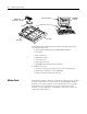
Using WinABMS Software 4-9 Marker Card Spacer Install pen in the top slot of the carousel Base Plate 3. Make sure the ink is flowing properly from the pen tip by drawing some test lines (refer to the instructions included with the pen). 4. Install pen in the top slot of the carousel. 5. Click on Plot under the File heading or click on the Plot Tool. To plot one marker card: 1. Repeat steps 1-4 under To Plot An Entire File. 2.
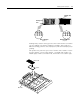
4-10 Using WinABMS Software One Marker Card One Branch One Marker Note: Use thumbs and index fingers to apply pressure to “snap” the markers free.Nevertwistthemarkerstobreakthemfree.Twistingwillresultinuneven breaks. Deleting a File To delete a File: 1. Use the Windows File Manager to delete files.
Chapter 5 Importing Data Chapter Objectives This chapter describes how to: • Import Data from Other Sources • Convert a Project File from ABMS 2.0 (DOS) Importing Data from Other Sources You can generate a program to create a WinABMS file with a software program that supports .txt or .csv files (CAD, Microsoft Word, Excel). When you import this text file to WinABMS, the code is automatically converted to a WinABMS formatted file.
5-2 Importing Data Spreadsheet one one one two two two Markercard one one one two two two To import a source program file: 1. Select(highlight)themarkerwhereyouwouldliketheimporteddatato start. The imported data will start at that marker, then flow in sequence into the markers following the one you selected. Note: If more than one marker is selected, then the imported information will only appear in the markers selected.
Importing Data 5-3 Note: Select All files from the Files of type box when you wish to import .txt files. 4. Click on Open. Converting an ABMS Project File This section shows how to convert a project file from the ABMS software into WinABMS. Note: If multiple types of markercards were saved in the ABMS file, then WinABMS will open a separate file for each markercard type found in the ABMS file. To convert a project file from ABMS: 1. Click on Convert under the File heading. 2.
Chapter 6 Custom Marker Card Geometries Chapter Objectives This chapter describes how to: • Use the Tool Bar • Create a Custom Marker Card Geometry • Open an existing Custom Marker Card Geometry • Edit a Custom Marker Card Geometry • Save a Custom Marker Card Geometry • Test Plot Custom Marker Card Geometry • Delete a Custom Marker Card Geometry The Tool Bar The GeoEdit software has a Tool Bar that can be used for shortcuts for the following commands.
6-2 Custom Marker Card Geometries Creating a Custom Marker Card Geometry This section describes how to create a Custom Marker Card Geometry. To create a Custom Marker Card Geometry: 1. Double Click on the GeoEdit icon. Note: You must completely exit from WinABMS before starting GeoEdit. 2. Click on New under the File heading or click on the New Geometry Tool. Note: To modify this new geometry, refer to section on Editing a Custom Marker Card Geometry.
Custom Marker Card Geometries 6-3 4. Click on the desired geometry. 5. Click OK. Editing a Custom Marker Card Geometry This section describes how to edit a Custom Marker Card Geometry. To edit a Custom Marker Card Geometry: 1. Double Click on the GeoEdit icon. Note: You must completely exit from WinABMS before starting GeoEdit. 2. Click on Open under the Fileheading or click on the Open Geometry Tool. 3. WhentheOpenGeometryMenuappearsclickonthedatabasewhich contains the desired geometry . 4.
6-4 Custom Marker Card Geometries 8. Click OK. 9. Click on Matrix under the Edit heading or click on the Edit Matrix Tool. 10. When the Edit MatrixSetting Menu appears enter the desired Origin settings for the X and Y coordinates. The Origin setting is the location of the upper left corner of the upper left marker on the geometry. Note: All measurements in the Edit Matrix Setting Menu are in millimeters . 11. Enter the desired dimensions for the markers.
Custom Marker Card Geometries 6-5 16. Click on Pen Priming under the Edit heading or click on the Pen Priming Tool. Note: The plotter will draw the pen priming line ten times to ensure that ink is flowing before plotting the markers. 17. Select the coordinates for the line. Note: This line should be placed outside of the matrices and info fields so it will not interfere with any marker text. 18. Click on OK.
6-6 Custom Marker Card Geometries Test Plotting a Custom Marker Card Geometry This section describes how to test plot a Custom Marker Card Geometry. This is used to see whether matrix settings need to be adjusted. To test plot a Custom Marker Card Geometry: 1. Click on Plot under the File heading or click on the Plot Tool. 2. WhenthePlotSettingsMenuappearsclickonthebaseplateslotwhere you would like to test plot your marker card. 3.
Chapter 7 Troubleshooting and Maintenance Chapter Objectives This chapter describes how to: • Troubleshoot the marking system • Perform routine maintenance • Clean the plotter pens Using the Troubleshooting Chart Table 7.A is a troubleshooting chart. This chart lists the most common operatingproblems,probablecauses,andstepstocorrecttheproblem.Ifyou encounter a problem that is not listed in the table, contact Allen-Bradley Technical Support at (440)646-5800.
7-2 Troubleshooting and Maintenance Troubleshooting Chart Table 7.A Troubleshooting Chart Problem Probable Cause(s) Corrective Action(s) Plotter does not power up. 1. Plotter not plugged in. 2. Improper connection to power source. 1. Verify that plotter is plugged in. 2. Verify 110/220 VAC, 50/60 Hz voltage at power source. No communications between plotter and computer. 1. Plotter DIP switches not set properly. 2. Faulty communications cable. 3. Wrong COM port selected. 1.
Troubleshooting and Maintenance Plotter Maintenance 7-3 The plotter has several sliding surfaces. These surfaces do not require any lubrication.However,dustandlintmayadverselyaffectplotterperformance. Use a dust cover to keep the plotter as clean as possible. To clean the plotter: 1. If necessary, clean the plotter with a soft lint–free cloth slightly dampened with a neutral detergent. DO NOT use abrasives.
7-4 Troubleshooting and Maintenance To clean refillable plotter pens: 1. Remove ink well. (Note: 1492-PLINKCART, disposable ink cartridge is neither cleanable nor refillable.) 2. Remove gray pen sleeve. 3. Open cleaning pot (1492-PLCLEAN). 4. Place pen tip, pen sleeve, and ink well into 1492-PLCLEAN. 5. Add cleaning solution (1492-PLSOLN). 6. Close 1492-PLCLEAN and shake. 7. Open 1492-PLCLEAN. 8. Remove ink cartridge, pen sleeve, and pen tip then thoroughly dry these items.
Appendix A RS-232 Communications Cable Thisappendixshowsthecommunicationscableconfigurationfortheplotter system.Usetheappropriatecableconfigurationdiagramifyouwanttocreate your own cable. Table A.1 Cable Configuration (9-25 pin) CPU (9-pin FEMALE) Plotter (25-pin MALE) 1 4 2 2 3 3 4 5, 6 5 7 6, 8 20 7 8 Table A.
A-2 RS-232 Communications Cable Graphical Cable Configuration CPU (9 pin FEMALE) 1 2 3 4 5 6 7 8 9 Plotter (25 pin MALE) 1 2 3 4 5 6 7 8 20 CPU (25 pin FEMALE) 1 2 3 4 5 6 7 8 20 Plotter (25 pin MALE 1 2 3 4 5 6 7 8 20
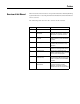
Appendix B Marker Card Reference Note: The stated Maximum Characters and Maximum Rows are recommendedvaluesusingasixpointfont.Thesevaluescanbeexceeded,but legibility will be diminished. Maximum Marking Parameters* Marker Orientation Horizontal Vertical Cat. No.
B-2 Marker Card Reference Marker Orientation Horizontal Vertical Cat. No. Number of Markers Width Height Rows Characters per row Rows Characters per row 1492-MR15, -AL15 (12mm) 20, 560 12 15 6 10 5 12 1492-N5 (5mm) 940 5 9 4 4 2 8 1492-N5 (6mm) 800 6 9 4 5 2 8 1492-N5 (6.1mm) 800 6, 1 9 4 5 2 8 1492-N5 (8.73mm) 540 8.73 9 4 7 3 8 1492-N5 (10.31mm) 460 10.31 9 4 9 4 8 1492-N43 4.
Glossary active — The window (application file or screen) or object that is currently selected. Only one window can be active at a time. If a window is active, its title bar is highlighted to differentiate it from other windows. If an object is active, it has handles. Windows or objects that are not selected are inactive. alphanumeric — The character set containing letters, numbers, punctuation marks and symbols. base plate — A plate that is attached to the top of the plotter.
Index A Accessories . . . . . . . . . . . . . . . . . . . . . . . 1-6 Adjusting Font Size and Width . . . . . . . . . 4-5 R C Calibrating the Plotter. . Clearing Marker Text . . Copying Marker Text . . Copying the Installation Creating a Geometry . . Creating a New File . . . ..... ..... ..... Disks. ..... ..... . . . . . . . . . . . . . . . . . . . . . . . . . . . . . . . . . . . . . . . . . . . . . . . . . . . . . . 3-7 4-6 4-6 2-1 6-2 4-2 D Deleting a File . . . . . . .
Publication 1492-UM001E-EN-E - July 2002 2 Supersedes Publication 1492-UM001D-EN-P - February 2002 © 2002 Rockwell International Corporation. Printed in the U.S.A.