
Owner's manual
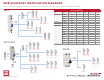

MCB ACCESSORY INSTALLATION DIAGRAMS
Note: These diagrams show the maximum number of accessories and the order allowed.
1489-M
1492-SP, 1492-D
1492-RCD
Shunt Trip
Shunt Trip
Signal
Contact
Signal
Contact
(C.O.)
Signal
Contact
(C.O.)
Signal
Contact
(C.O.)
Signal
Contact
Signal
Contact
Signal
Contact
Aux.
Contact
Aux.
Contact
Left
Mount
Right
Mount
Right
Mount
Bottom
Mount
Right
Mount
Aux.
Contact
Aux.
Contact
(C.O.)
Aux.
Contact
(C.O.)
Aux.
Contact
(C.O.)
Aux.
Contact
(C.O.)
Aux.
Contact
(C.O.)
Aux.
Contact
(C.O.)
Aux.
Contact
(C.O.)
Aux.
Contact
(C.O.)
Aux.
Contact
(C.O.)
Aux.
Contact
(C.O.)
Aux.
Contact
(C.O.)
Aux.
Contact
(C.O.)
Aux.
Contact
(C.O.)
Aux.
Contact
Aux.
Contact
Aux.
Contact
Aux.
Contact
Aux.
Contact
Aux.
Contact
Aux.
Contact
Aux.
Contact
+
+
+
+
+
+
+
+
+
+
+
+
+
+
+
+
Publication 1492-RM001A-EN-P – May 2014 Copyright © 2014 Rockwell Automation, Inc. All Rights Reserved. Printed in USA.
Accessory Compatibility
Type Catalog No. Mounting Location Contacts 1489-M 1492-SP, 1492-D 1492-RCD
Shunt Trip 1489-AMST1 Right –
✓
1489-AMST2 Right –
✓
189-AST1 Right –
✓
189-AST2 Right –
✓
Signal Contact 1489-AMRS3 Right 1 C.O.
✓
Aux/Signal Contact 189-ASCR3 Right 1 C.O.
✓✓
Auxiliary Contact 1489-AMRA3 Right 1 C.O.
✓
189-AR3 Right 1 C.O.
✓✓
189-AR11 Right 1 N.O. + 1 N.C.
✓✓
189-AR02 Right 2 N.C.
✓✓
189-AR20 Right 2 N.O.
✓✓
189-AL11 Left 1 N.O. + 1 N.C.
✓
189-AL02 Left 2 N.C.
✓
189-AL20 Left 2 N.O.
✓
189-AB01 Bottom 1 N.C.
✓
189-AB10 Bottom 1 N.O.
✓
N.O and N.C. contacts may not be combined with shunt trips or C.O. (change-over) type contacts.