ClearMark™ Printer Catalog Numbers 1492-PRINT110, 1492-PRINT220 User Manual
Important User Information In no event will Rockwell Automation, Inc. be responsible or liable for indirect or consequential damages resulting from the use or application of this equipment. The examples and diagrams in this manual are included solely for illustrative purposes. Because of the many variables and requirements associated with any particular installation, Rockwell Automation, Inc. cannot assume responsibility or liability for actual use based on the examples and diagrams.
Table of Contents Preface Chapter 1: Product Overview Introduction . . . . . . . . . . . . . . . . . . . . . . . . . . . . . . . . . . . . . . . . . . 1-1 Description . . . . . . . . . . . . . . . . . . . . . . . . . . . . . . . . . . . . . . . . . . 1-1 Display Functions . . . . . . . . . . . . . . . . . . . . . . . . . . . . . . . . . . . . . 1-5 Rotating the Operating and Control Panel (Display) . . . . . . . . . . 1-8 Chapter 2: Initial Set Up Unpacking and Inspecting . . . . . . . . . . . . . . . . . .
Preface Preface Information Concerning the Technical Documentation The documentation for the ClearMark printer consists of the following parts: • User Manual (Publication Number 1492-UM008A-EN-P) This manual is found on the CD. It has been written for personnel who will be operating, performing simple maintenance, and service work on the printer. • Quick Start Guide (Publication Number 1492-QS002A-EN-P) These instructions have been written for personnel who will be installing and setting up the printer.
Preface Safety and the Environment Safety Instructions Depending on the model, the ClearMark printer is configured with a power supply for AC voltage of either 110V or 220V. ATTENTION: Only plug the printer into a grounded outlet. Turn off all relevant devices (computer, printer, or accessories) before connecting or disconnecting the devices. The printer should only be operated in a dry environment with no exposure to moisture (splashed water, fog, etc.).
Preface Application The individual marking of equipment can be quickly and conveniently carried out using the ClearMark printer. The ClearMark printer uses a innovative, permanently-readable printing process to print marker cards for switching devices, machines, terminal blocks, cables, conductors and other industrial controls. A secure and permanent label is made possible and is resistant to wiping and scratching, UV stability, and high printing resolution for all marker cards.
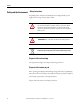
Preface Figure P.2 - Warning Label on Device ATTENTION: Do not disassemble the printer! Do not open the printer housing! This exposes you to a risk of injury! There are no serviceable parts inside the printer. You will forfeit all rights under the warranty if you open the cover! Safety Precautions Read the following instructions carefully before starting up the ClearMark printer. Observe the warnings and notices on the ClearMark printer at all times. • The printer weighs approx. 65 lb. (30 kg).
Preface • Do not open the device when it is printing! ATTENTION: Only connect the printer to a properly grounded and correctly-fused outlet. Do not use an outlet already being used by devices that are turned on and off at regular intervals, such as photocopiers or fans. Do not connect the ClearMark printer to either a switched or a timer-controlled outlet.
Preface ATTENTION: Do not operate the ClearMark printer without a cover. Never reach into the printer openings while the printer is operating. • The ClearMark printer should always be transported in a horizontal position. Improper transport can lead to leaked ink and contamination or damage to the printer.
Chapter 1 Product Overview Introduction This chapter provides a brief overview of the features and functionality of the ClearMark Printer Description The ClearMark printer is a printing system for labelling Allen-Bradley markers. Primarily, the Bulletin 1492 Marker Cards. The data is created on a PC using the ClearTools labelling software. This software is also used for the configuration of the printer drivers.
Chapter 1 Product Overview Figure 1.2 - Connections Power Cord Network Cable (if desired) USB Cable Figure 1.3 - Enclosure Recessed Grips Figure 1.
Product Overview Chapter 1 Figure 1.5 - Loader and Maintenance Cover for Ink Waste Pad Figure 1.6 - Maintenance Cover for Printing System Figure 1.
Chapter 1 Product Overview Figure 1.8 - Input (Loader) Figure 1.
Product Overview Chapter 1 Figure 1.10 - Display Display Functions Power Use this button to turn the printer on and off. In order to turn on the printer, press the button until it is illuminated. After the printer has been turned on, the [Power] button blinks until the printer is operational. The button then remains illuminated. The Power button also blinks when the printer is processing data. When the printer is turned off, the button blinks slowly until the printer is fully powered off.
Chapter 1 Product Overview Display This shows the current status of the printer and any error messages. Menu Press this button to change or view the printer settings. Online This button indicates whether the printer is offline or online. Press this button in order to switch between the offline and online modes. When the button is lit, the printer is online and data can be received from the host computer. When not illuminated, the printer is offline and data is not received.
Product Overview Chapter 1 Press this button in order to execute the menu command shown on the display (Enter Key). Heating 1 Activates or deactivates the full heat output of the fuser. Heating 2 Activates or deactivates the reduced heat output of the fuser. Loader Activates or deactivates the loader function (feeds the marker card through). Inlay Activates or deactivates the inlay function (for printing materials other than marker cards).
Chapter 1 Product Overview Status / Error Display This is the status indicator when printing. Blue: • • • • The print job is being processed. There are additional print jobs in the queue. A general process error has occurred while processing this print job. Ink collecting tray is full Orange: • Ink collecting tray is almost full. Data IN LED This LED flashes when the printer is receiving data from the computer. The display is illuminated when pending data is waiting to be printed.
Chapter 2 Initial Set Up Unpacking and Inspecting Carefully take all parts out of the packaging. Always use two people to move the printer and make use of the grips available. IMPORTANT Keep original packaging for future shipment. Figure 2.1 - Clearance Requirements - in. (mm) 3.94 (100) Grip Grip 9.84 (250) 7.87 (200) 9.84 (250) Grip Grip 3.94 (100) Figure 2.1 shows the necessary clearance requirements for optimal air circulation and insertion and removal of the marker cards.
Chapter 2 Initial Set Up • • • • • • Quick Start Guide ClearMark Printer user manual (this document) ClearTools Software user manual Printer driver and ClearTools software CD Two marker cards (Cat. No. 1492-M5X5) Output rail IMPORTANT Set Up A LAN cable and extra ink cartridges are not shipped with printer Select a suitable location for the ClearMark printer, considering the following factors: • Place the ClearMark printer on a flat, stable surface larger than the base area of the printer.
Initial Set Up Chapter 2 Output Rail Installation Insert the output rail so that it snaps into position. Figure 2.2 - Output Rail Installation Connecting the power cord The supply voltage must correspond to the system voltage given on the ClearMark printer serial label. Connect the plug-in power connection to a nearby grounded outlet, ensuring it is easily accessible. ATTENTION: Only connect the printer to a properly grounded and correctly-fused outlet.
Chapter 2 Initial Set Up ATTENTION: Do not carry out repairs to the device. Unplug the ClearMark Printer and contact a qualified service engineer if either of the following occurs: • The power cord is worn or damaged. • The plug is worn or damaged. Power supply Connect the power cord to the ClearMark Printer and grounded outlet (220-240 VAC or 100-120 VAC). Make sure that the plug is completely inserted. Top fuse: • 10 A / delay-action 230V AC • (12.
Chapter 3 Installing the Printer Driver Introduction All necessary printer driver settings are made automatically by the ClearTools software. Before you begin with the installation of the software and the printer driver, insert the "Printer Driver & Software" CD-ROM (included in delivery) into the CD-ROM drive of your computer. The CD starts automatically and shows the language-selection screen (shown below). If the CD does not start automatically, start the Setup.exe file found on the CD. Figure 3.
Chapter 3 Installing the Printer Driver Windows XP/Windows 2000 USB port - Windows XP/ Windows 2000 Figure 3.3 - License Agreement 1. Accept the license agreement and click [Next]. Figure 3.4 - Connecting the Printer 2. Select the USB cable option and click [Next].
Installing the Printer Driver Chapter 3 Figure 3.5 - Installing the Printer Driver 3. Make sure the printer is turned off. Click [Next]. Figure 3.6 - Automatic Recognition of the USB Connection 4. Turn on the printer when its window appears. The printer driver will now be installed. Figure 3.
Chapter 3 Installing the Printer Driver 5. Do not define the printer as the default printer. Click [No]. Figure 3.8 - Status Monitor 6. Choose "Newer Display Status Monitor" Figure 3.9 - Installation of Printer Driver Successful 7. Click [Finish].
Installing the Printer Driver Chapter 3 Network Connection - Windows XP/ Windows 2000 On the printer press the Menu key, the arrow keys and the Enter key to select the submenu 'Host interface 'followed by 'Network setup' and 'IP address'. Press the Enter key again to display the IP address of the printer. Now enter in your Web browser (please enter the printer IP address using the following format: XXX.XXX.XXX).
Chapter 3 Installing the Printer Driver Figure 3.11 - License Agreement 1. Accept the license agreement and click [Next]. Figure 3.12 - Connecting the Printer 2. Select the LAN Connection option and click [Next].
Installing the Printer Driver Chapter 3 Figure 3.13 - Installing the Printer Driver 3. Select the option shown above and click [Next]. Figure 3.14 - Default Printer 4. Double click on the printer names to display the printer settings. 5. Click [Continue].
Chapter 3 Installing the Printer Driver Figure 3.15 - Status Monitor 6. Deactive the status monitor and click [Next]. Figure 3.16 - Installation of the Printer Driver Successful 7. Select the option shown above and click [Finish]. 8. Open Start →Settings →Printer (Windows 2000), or Start → Printer and Fax (XP). Select the printer which you have just installed and then right click to get to properties.
Installing the Printer Driver Chapter 3 Figure 3.17 - Printer Driver Properties 9. Click on the "Ports" tab and then [Add Port]. Figure 3.18 - Printer Connections 10. Select "Standard TCP/IP Port" and [New Port].
Chapter 3 Installing the Printer Driver Figure 3.19 - TCP/IP Printer Port 11. Click [Next]. Figure 3.20 - Add Port 12. Enter the hostname (see above- RNPAXXXXX) of the printer in this window. (Here, XXXX is the number of your printer.
Installing the Printer Driver Chapter 3 Figure 3.21 - Exiting the Install Wizard The connection is then added. 13. Verify that a connection to the selected printer exists in Device. 14. In the dialog box for the finished installation, click [Finish]. Windows VISTA USB Port - Windows VISTA 1. Insert the "Printer Driver & Software" CD-ROM (included in delivery) into the CD-ROM drive of your computer. The CD starts automatically and waits for the language to be selected.
Chapter 3 Installing the Printer Driver Figure 3.22 - License Agreement 1. Accept the license agreement and click [Next]. Figure 3.23 - Printer Port 2. Select the option Connect with USB cable then click [Next].
Installing the Printer Driver Chapter 3 Figure 3.24 - Installing the Printer Driver 3. Make sure that the printer is turned off. Click [Next]. Figure 3.25 - Automatic Recognition of USB Connection 4. When this window appears, turn on the printer. The printer driver will now be installed.
Chapter 3 Installing the Printer Driver Figure 3.26 - Default Printer 5. Do not set this printer as the system default printer. Click [No]. Figure 3.27 - Status Monitor 6. Deactivate the status monitor and click [Next].
Installing the Printer Driver Chapter 3 Figure 3.28 - Installation of the Printer Driver Successful 7. After you click [Finish], the installation of the printer driver is finished. Network Connection - Windows VISTA 1. On the printer press the Menu key, the arrow keys and the Enter key to select the submenu 'Host interface' followed by 'Network setup' and 'IP address'. 2. Press the Enter key again to display the IP address of the printer. 3.
Chapter 3 Installing the Printer Driver Figure 3.29 - Internet Options Figure 3.30 - LAN Settings 4. Once you have carried out the procedures described above, take the CD-ROM 'Printer Driver & Software' included in the range of supply and insert it into the CD-ROM drive of your PC. The CD-ROM will start automatically. At this point you must select a language.
Installing the Printer Driver Chapter 3 If the CD does not start automatically click SETUP.EXE on the CD. Ensure you have administrator rights for your local computer. 5. On the main menu 'Printer Driver & Software' select Printer drivers→ ClearMark Printer→VISTA/XP/Win2000. 6. The Operating System will now issue a message stating that "an unidentified program wants to access your computer". Click [Allow]. The installation process will now start. Figure 3.31 - License Agreement 7.
Chapter 3 Installing the Printer Driver Figure 3.32 - Connecting the printer 8. Select the LAN Connection option and click [Next]. Figure 3.33 - Installing the Printer Driver 9. Select the option shown above and click [Next].
Installing the Printer Driver Chapter 3 Figure 3.34 - Default Printer 10. Double click on the printer names to display the printer settings. 11. Click [Continue]. Figure 3.35 - Status Monitor 12. Deactivate the status monitor and click [Next].
Chapter 3 Installing the Printer Driver Figure 3.36 - Installation of Printer Driver Successful 13. Select the option shown above and click [Finish]. 14. Open Start → Control Panel and under "Hardware and Sound" select [Printer]. Select the printer which you have just installed and then right click to get to properties. Figure 3.37 - Printer Driver Properties 15. Select the "Ports" tab and then [Add Port].
Installing the Printer Driver Chapter 3 Figure 3.38 - Printer Connections 16. Select "Standard TCP/IP port" and click [New Port]. Figure 3.39 - TCP/IP Printer Port 17. Click [Next].
Chapter 3 Installing the Printer Driver Figure 3.40 - Add Port 18. Enter the hostname (see above - RNPAXXXXX) of the printer in this window. (Here, XXXXX is the number of your printer.) Figure 3.41 - Exiting the Install Wizard The connection is then added. 19. Verify that a connection to the selected printers exists in "Device". 20. In the dialog box for the finished installation, click [Finish].
Chapter 4 ClearTools Software Installation Installing the ClearTools Software Please note that this printing system is optimized for Microsoft Windows 2000, XP and VISTA. For installation and operation, you require a basic knowledge of Microsoft Windows. Before you begin with the installation of the software and the printer driver, insert the "Printer Driver & Software" CD-ROM (included in delivery) into the CD-ROM drive of your computer. The CD starts automatically. Figure 4.
Chapter 4 ClearTools Software Installation 2. The installation starts automatically and the installation assistant appears on the screen. Please follow the instructions in the installation assistant by clicking [Next]. 3. Accept the license agreement and click [Next]. 4. Click [Next] to install default folder. 5. Click [Install]. Figure 4.2 - Installation Wizard 6. After the installation successfully concludes, click [Finish]. Figure 4.3 - Completing installation 7.
ClearTools Software Installation Chapter 4 2. In the Options window, select the "ClearMark" folder. Figure 4.4 - Configuring ClearMark 3. Click [Execute Printer driver configuration]. 4. Select the print quality. The recommended setting is "Quality Print". Please select "Premium Print" only when printing intricate graphics. This will result in more ink usage and a slower print process. 5. Confirm the driver settings by clicking [Finish]. Figure 4.
Chapter 4 ClearTools Software Installation Please read and refer to the Quick Start Guide and ClearTools manual, found on the "Printer Driver & Software" CD. After the software installation these are available on your computer. Adjust Marker Type In order to compensate for physical changes to the marker cards, refer to specific card calibration on page 5-5. Please read and refer to the ClearTools manual, found on the "Printer Driver & Software" CD.
Chapter 5 Calibration General Calibration Calibrating the ClearMark Printer Note: Affects all Cards 1. To open ClearTools, Go to: Start→Programs→Rockwell Automation→ ClearTools→ClearTools. 2. Double click on "1492-M5X5" in the variant list. 3. In the first column, 5 marker tags down, place a capital "X" as shown. ( See Figure 5.1.) Note: It is critical to select this tag. Figure 5.1 - 3 4.
Chapter 5 Calibration 6. In the pull down menu select the GelSprinter GX3000/3050N printer . See Figure 5.2. Figure 5.2 6 7 9 8 13 7. Click [Map]. (The 1492-M5X5 is now linked to this printer) 8. Click [OK], with the "As Printer" selected. See Figure 5.2. 9. Click [Calibration]. 10. Verify a value of "7" in the box marked "Left" and a "66" in the box marked "Top". See Figure 5.3. 11. Click [Save]. Figure 5.3 11 10 12. Load the 1492-M5X5 card. 13. Click on Print.
Calibration Chapter 5 18. After making a change, Click [Save]. Then click [Print] to check the card. a. If centered go to step 19, If not go back to step 15. Figure 5.4 If “X” appears on this half of the card increase the “Left” number to move it back to center. If “X” appears on this half of the card decrease the “Left” number to move it back to center. Figure 5.5 If “X” appears on this half of the card increase the “Top” number to move it back to center.
Chapter 5 Calibration 19. Place a capital "X" in the upper right corner as shown( See Figure 5.6 ). You can leave the "X" in the first column because it will not move with these upcoming changes. 20. Go to File→Print, and click [Print]. Figure 5.6 - 19 21 21. If the "X" is centered you are done calibrating and are ready to print. (See section on printing). 22. If the "X" is not centered. Go to File→ Set Printer Correction. ( See Figure 5.7). Figure 5.
Calibration Chapter 5 23. See Figure 5.8 for horizontal adjustments 24. See Figure 5.9 for vertical adjustments. Figure 5.8 - If “X“ appears on this half of the card decrease the “Actual Width (X)“ number to move it back to center. If “X“ appears on this half of the card increase the “Actual Width (X)“ number to move it back to center. Figure 5.9 If “X“ appears on this half of the card increase the “Actual Height (Y) “ number to move it back to center.
Chapter 5 Calibration Figure 5.10 - 1 2. Print the test card 3. If the text is not centered, go to File→ Adjust Marker Type (See Figure 5.11) Adjusting Offset of Cards Figure 5.11 - 10 11 13 14 5 6 4. If the "X" on the test card is not centered, make adjustments to the offset values. Note: If the "X" is centered, leave the offset values at 0. 5. To make horizontal adjustments, see Figure 5.12. 6. To make vertical adjustments, see Figure 5.13.
Calibration Chapter 5 Figure 5.12 If “X” appears on this half of the card increase the “Offset X (a)” value to move it back to center. If “X” appears on this half of the card decrease the “Offset X (a)” value to move it back to center. Figure 5.13 If “X” appears on this half of the card increase the “Offset Y (b)” value to move it back to center. If “X” appears on this half of the card decrease the “Offset Y (b)” value to move it back to center.
Chapter 5 Calibration Note: For examples of drifting text, (See Figure 5.14 and Figure 5.15). Use the yellow center lines as reference. Figure 5.14 - Note to edit: Center all lines on each column of the marker tags 10. If the text gradually drifts to the right of the tags, decrease the [Width (X):] value. 11. 11. If the text gradually drifts to the left of the tags, increase the [Width (X):] value 12. If the height is not set correctly, the text will gradually drift out of alignment from top to bottom.
Chapter 6 First Time Use Checklist Overview of the necessary steps: 1. Turn on ClearMark printer. 2. Start ClearTools software. 3. Setup printer in ClearTools. 4. Calibrate the ClearMark printer. 5. Select marker card and enter text. 6. Insert the marker cards which correspond to the ClearTools file in the ClearMark printer loader. 7. On the ClearMark printer select the correct heat setting for the inserted marker cards. 8. Start printing with ClearTools.
Chapter 6 First Time Use Description of the Marker Card Figure 6.1 - Description of marker card C A B D A. Project marking surface B. Marking surface C. Side strips D. Feed-in direction Insert as shown Make sure the marker cards are inserted in the correct way with the project marking surface facing towards the ClearMark printer. Figure 6.2 - Insertion instructions Insert the marker cards into the loader so that they are touching the end stop.
First Time Use Chapter 6 ATTENTION: Do not exceed the maximum permitted stacking height when filling the loader. ATTENTION: You can insert complete or half marker cards. Do not mix complete or half marker cards. Stacking heights Do not stack the marker cards above the height of the loader paper stop. Figure 6.3 - Stacking heights in the loader ATTENTION: Under certain circumstances, the card separation process may malfunction when the maximum amount of marker cards is inserted.
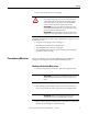
Chapter 6 First Time Use Recommendations: Marker Type Catalog Numbers Snap-in individual markers: Color 600 dpi 1200 dpi 1492-M, -MC, -MCS, -MN, -SM H1 H1 1492-MCW H2 H2 H2 H2 H1 H1 1492-MR Snap-in linked markers Settings 1492-MS White Snap-in hinged markers 1492-MH H1 H1 Cable markers 1492-MW H1 H1 Self-adhesive cable markers 1492-MWL H1 H1 Wire markers 1492-MWC H2 H2 All Colors Note: If Heating 1 causes bubbles on the surface, please change to Heating 2.
Chapter 7 Maintenance General Maintenance Even if the printer will not be used for a prolonged period, do not turn it off. When using again, please observe the following: The print-head nozzles can become dried up or clogged. You should periodically use the printer in order to avoid such damage. The printer should be turned on at least once a week for a few minutes. If you do not use the printer for a long time, always check first to see if the nozzles are clear.
Chapter 7 Maintenance Figure 7.1 - Print head cleaning option Cleaning the print head The cleaning process cleans the print head when a printed image appears slight blurred. Please take the following steps: 1. Select "Cleaning type 1" and the corresponding print heads. Figure 7.2 - Cleaning the print head 2. Click [Execute Head-Cleaning]. 3. The cleaning process is initiated. This can take several minutes to run. 4.
Maintenance Chapter 7 Head flushing The head-flushing process cleans the print head when a printed image appears very blurred. The flushing process uses more ink than the head cleaning. Please take the following steps: 1. Select "Cleaning type 2" and the corresponding print heads. Figure 7.3 - Thorough cleaning 2. Click on [Execute Head-Flushing]. 3. The cleaning process is initiated. This can take several minutes to run. 4.
Chapter 7 Maintenance Replacing the Ink Cartridges Handling Ink Cartridges • Store unopened ink cartridges in a cool and dry place, preferably in a refrigerator at +40 °F (+4 °C). • Before using an ink cartridge that has been stored in a colder place, allow the cartridge to adjust to the room temperature for at least three hours. • Install ink cartridges immediately after removing from the packaging. The print quality can be impaired if an ink cartridge is left unpacked for any length of time before use.
Maintenance Chapter 7 Ink Cartridge Installation Ink cartridge from starter kit Insert ink cartridges into corresponding carriers Snap in place • 1 x black, 1 x cyan, 1 x magenta, 1 x yellow Figure 7.4 - Color System Figure 7.5 - Inserting the ink-cartridge carrier 1. Open the ink cartridge cover. 2. Remove the ink cartridge carrier.
Chapter 7 Maintenance 3. Remove ink cartridge. 4. Install new ink cartridge. 5. Check the alignment and the assembly of the ink cartridge carrier. Then carefully place it into the printer using the following guidelines. Pay special attention to whether you are installing black or colored inks. 6. Press on the middle of the ink-cartridge carrier and push in until it snaps into place. 7. Repeat this step for all ink-cartridge carriers. 8. Close the ink-cartridge cover.
Maintenance Chapter 7 Figure 7.6 - Replacing the ink collector unit 4. Place the full ink collector unit into the provided bag and dispose. 5. Insert the new ink collector unit into the printer. 6. Close the cover so that it snaps firmly into place. 7. Turn ON the printer. 8. A message in the printer display requests you to reset the internal counter or the display continues to display the message: Replace Ink Collector Unit 9. Press the [Menu] key 10.
Chapter 7 Maintenance General Cleaning Clean the outside of the printer regularly by wiping it with a soft cloth that is either dry or moistened with water. If the dirt does not come off, wipe the printer with a cloth moistened with a neutral cleaning agent. Next wipe with a cloth moistened with water and then with a dry cloth. ATTENTION: Do not use volatile chemicals such as benzene, thinning fluid or insecticide on the printer.
Maintenance Chapter 7 5. Place the printer carefully into the box. Be certain to lift the printer using only the recessed grips provided. 6. Put the protective foam into place. 7. Close and seal the box.
Chapter 7 Maintenance Notes: 7-10 Rockwell Automation Publication 1492-UM008A-EN-P - June 2010
Chapter 8 Troubleshooting LED Displays See the following table for the meaning of the LED Displays Table 8.1 - LED Error Displays LED Type Cause Troubleshooting Information Turn off the system and then turn it on again in order to initialize. The marker card is then transported out of the printer. Transport A marker card may be stuck in the heating unit Flashing If the card is not fed out of the printer, proceed as follows: • Turn off the printer and wait until it has cooled off.
Chapter 8 Troubleshooting General Troubleshooting If the print results are not satisfactory or the printed image is too weak or is spotted, check the printer status. Check the printer status Print out an example marker card in order to check if all print-head nozzles are emitting ink properly. If necessary, carry out a normal print head cleaning or a head flushing.
Troubleshooting Chapter 8 Ink cartridges should only be used before the expiration date. • Is the print quality setting correct? Using the ClearTools software, make sure that the printer driver is set correctly to either Standard or Quality (See page 4 - 3). Dirty or spotted printouts If the printed marking surface is dirty or spotted, focus on the following: • Have you touched the unprinted marker card? Avoid touching the unprinted marking surface before the printing process.
Chapter 8 Troubleshooting Switch off the device then switch it on again. The card caught in the device will be transported out of the device. Control Panel Messages See the following table for the meaning of messages displayed on the control panel Error Message Meaning An error has occurred. Power off/on call service if error reoccurs Switch the printer off and then on again. If the message is still displayed contact your local Allen-Bradley distributor or Rockwell Automation technical support.
Troubleshooting Error Message Load Paper: Tray# or Form Feed Chapter 8 Meaning The loader is empty or the print system is currently heating up. Fill the loader. Remove Misfeed Bypass Turn the printer off, then back on. Remove Misfeed Duplex Turn the printer off, then back on. Remove Misfeed Tray 1 There is a paper jam in the loader. Clear the jam in the loader. Remove Misfeed Top Cover Turn the printer off, then back on.
Chapter 8 Troubleshooting Notes: 8-6 Rockwell Automation Publication 1492-UM008A-EN-P - June 2010
Appendix Technical Data Specifications Application Printing Allen-Bradley marker cards Printing technology Ink-jet process with heat fusing Print quality 600...1200 dpi Printer drivers RPCS driver; WIN XP/2000; VISTA Printing software ClearTools software recommended System requirements WIN XP/ 2000; VISTA Feed Automatic loader, maximum 20 marker cards Interface USB 1.1/ 2.0 and 10 Base-T/100 Base-TX Power supply 100...120V AC/ 4 A, 50/60 Hz or 220...
Rockwell Automation Support Rockwell Automation provides technical information on the Web to assist you in using its products. At http://www.rockwellautomation.com/support/, you can find technical manuals, a knowledge base of FAQs, technical and application notes, sample code and links to software service packs, and a My Support feature that you can customize to make the best use of these tools.