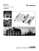
Plotter Kit Catalog Numbers 1492-PLTKIT User Manual
Important User Information Because of the variety of uses for the products described in this publication, those responsible for the application and use of this control equipment must satisfy themselves that all necessary steps have been taken to assure that each application and use meets all performance and safety requirements, including any applicable laws, regulations, codes and standards.
Table of Contents Preface Overview of this Manual . . . . . . . . . . . . . . . . . . . . . . . . . . . . . . . . . . . . . i Intended Audience . . . . . . . . . . . . . . . . . . . . . . . . . . . . . . . . . . . . . . . . . . ii Conventions . . . . . . . . . . . . . . . . . . . . . . . . . . . . . . . . . . . . . . . . . . . . . . . ii Ch. 1—Marking System Description Chapter Objectives. . . . . . . . . . . . . . . . . . . . . . . . . . . . . . . . . . . . . . . . Marking System Components . . . . . .
Table of Contents ii Troubleshooting and Maintenance—4 Appendix A Chapter Objectives. . . . . . . . . . . . . . . . . . . . . . . . . . . . . . . . . . . . . . . . 4-1 Using the Troubleshooting Chart . . . . . . . . . . . . . . . . . . . . . . . . . . . . 4-1 Required Equipment . . . . . . . . . . . . . . . . . . . . . . . . . . . . . . . . . . . . . . 4-1 Plotter Maintenance . . . . . . . . . . . . . . . . . . . . . . . . . . . . . . . . . . . . . . . 4-2 Cleaning Plotter . . . . . . . . . . . . . . .
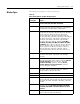
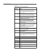
Preface Overview of this Manual This manual describes how to use components of the Allen–Bradley Plotter Kit to create and print markers for Bulletin 1492 Terminal Blocks and accessories. The following table describes the contents of this manual. ™ Chapter Title Contents Preface Provides an overview of the manual. 1 Marking System Description Provides a brief overview of the hardware and software. Includes a description of system accessories. 3 Operation of Plotter Describes plotter controls.
Preface Intended Audience Basic knowledge of the Microsoft Windows™ Operating System is required to operate the 1492-PLTKIT Plotter System. For ClearTools software instructions, refer to the user’s manual contained within the ClearTools software. Conventions This manual uses the following conventions: · Allen–Bradley Marking System software is referred to as ClearTools. · Marker refers to the individual tabs that snap onto a terminal block.
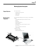
Chapter 1 Marking System Description Chapter Objectives This chapter describes: Marking System components Marker Cards Marker types Accessories Marking System Components The Terminal Block Marking System kit (Catalog No.
Marking System Description Allen–Bradley markers can be printed in either a horizontal or vertical direction. The ClearTools software displays a view of the markers as they would appear on the plotter. Marker Cards GND TB1 TB2 TB Plotting starts here Vertical Upside-Down Direction GND TB1 TB2 TB 1-2 TB TB2 TB1 GND Horizontal Upside-Down Direction GND TB1 TB2 TB Vertical Direction Horizontal Direction Plotting always starts in the upper left corner of the marker card.
Marking System Description Marker Types 1-3 The marking system supports a variety of marker types. Table 1.A Allen–Bradley Markers for Allen-Bradley Products Marker/Label Catalog No.
1-4 Marking System Description Table 1.A Allen–Bradley Markers for Allen-Bradley Products Marker/Label Catalog No.
Marking System Description 1-5 Table 1.A Allen–Bradley Markers for Allen-Bradley Products Marker/Label Catalog No.
1-6 Marking System Description Table 1.A Allen–Bradley Markers for Allen-Bradley Products Marker/Label Catalog No. Use With These Allen-Bradley Terminal Blocks and Other Products 1492-MS8X12 1492-H4, 1492-H5, 1492-H6, 1492-H7, 1492-RFB4*, 1492-RAFB4*, 1492-W10, 1492-WFB4*, 700-HA, 1492-W165, 1492-WG10, 1492-WG165 1492-MS8X17 700-HN204, 700-HN205 1492-MS9X20 1667 PanelConnect 1492-MS10X17 100-C, 100-D, 700-CF, 140, 193-E1, 193-E3, 1492-REC* 1492-MW9X24 Wire/cable from 6 AWG (from 16.
Marking System Description Accessories 1-7 Table 1.B Accessories Item Catalog No. Description Disposable Pen 1492–PLOTPEN25 Disposable ink pen with 0.25 mm tip Disposable Pen 1492–PLOTPEN35 Disposable ink pen with 0.
1-8 Marking System Description Table 1.
Marking System Description Table 1.
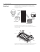
1-10 Marking System Description 1. Line up the number on the inlay with the notched locator on the base plate. 2. Slide right side of marker card under ledge on plotter plate. 3. Line-up first notch on the left side of the marker card to the notch on the plotter plate. 4. Press the left side on the marker card down on to the plotter plates. For plotter plates with the adhesive strip, refer to Adhesive Strip Preparation on page A-1. Installing Inlay onto Plate Installing Marker Card onto Plate Table 1.
Chapter 2 Initial Setup Chapter Objectives This chapter shows how to: • Set up the Plotter • Installing the Plotter Driver • Activating the Plotter with ClearTools Setup Location A dry, dust-free room is the ideal environment for the plotter. If possible, do not install the device in damp or very dusty areas. Do not expose the system to direct sunlight. Please ensure the connections on the right-hand side of the device are accessible all times.
2-2 Initial Setup Installing the Plotter Driver Installing the driver for the plotter 1492-PLTKIT Series E within Windows 2000 1. Login into your Computer using an account with administrative rights. 2. Connect the Plotter to your system and switch on the power. The “Found New Hardware Wizard” starts. Click on “Next”. 3. Choose “Search for a suitable driver for my device (recommended)” and then click “Next”.
Initial Setup 2-3 4. Choose “Specify a location” and click on “Next”. 5. In the opening window, click on “Browse” and select the subfolder “W2K” in the folder “Psetup” on your installation CD. Confirm with “Open” and then with “OK”. 6. Then click on “NEXT“. The installation begins now.
2-4 Initial Setup 7. During the installation a message appears stating “The software you are about to install does not contain a Microsoft digital signature… ” and asks “Do you want to continue the installation?” Click on “Yes”.
Initial Setup 2-5 8. Click on “Finish” to close the window. The driver for the connected device 1492-PLTKIT Series E is now installed and ready to use.
2-6 Initial Setup Installing the driver for the 1492-PLTKIT Series E within Windows Vista 1. Login into your Computer using an account with administrative rights. Before you begin installing the driver you need to know if you are running the 32-bit or the 64-bit version of Windows Vista on your computer. If you are not sure, you can open the following window: Start > Control Panel > System and Maintenance > System or Start > Control Panel > System (when using the classical view of the control panel).
Initial Setup 2-7 2. Go to “Start > Control Panel > Printers”. Then connect your 1492-PLTKIT Series E plotter to the system and switch on the power. If the driver is already installed, you will find your plotter in the list of Printers and Faxes. If the driver is not yet installed, the window “Found New Hardware” appears.
2-8 Initial Setup Click on ”Locate and install driver (recommended)”. 3. If a window appears, asking “Allow windows to search online....?” answer with “Don't search online”. 4. After the following window appears, insert the installation CD into the drive and click on “Next”.
Initial Setup 2-9 5. The recognized drivers on the CD are listed. Choose the entry …\Psetup\vista_64\1492_pltkit.inf (for the 64-Bit version of Windows Vista). or …\Psetup\vista_32\1492_pltkit.inf (for the 32-Bit version of Windows Vista) and click on “Next“, to start the installation. If this list does NOT appear (or you have stored the driver files at a different location on your computer), you can search for the driver files manually. 6.1. Click on “I don't have the disk. Show me other options.
2-10 Initial Setup Click on “Browse” and select the path Psetup\vista_32 or Psetup\vista-64, depending on whether you have a 32-bit or 64-bit version of Windows Vista. (In order to see which Windows Vista version you have, navigate to Start > Control Panel > System and Maintenance > System or Start > Control Panel > System.
Initial Setup 2-11 Confirm with “OK” and then “Next”. The installation starts now. 7. During the installation the following message appears: “Windows can't verify the publisher of this driver software”: Choose “Install the driver software anyway”. 8. After a successful installation Windows issues the following message. Press click on “Close” to complete the installation. 9. Reopen the window “Control Panel > Printers”. Your plotter should now appear in the list of Printers and Faxes.
2-12 Initial Setup Installing the driver for the 1492-PLTKIT Series E within Windows XP 1. Login into your Computer using an account with administrative rights. 2. Connect the Plotter to your system and switch on the power. The “Found New Hardware Wizard” starts. 3. Choose “Install from a list or specific location” and then click “Next”. 4.
Initial Setup 2-13 The driver will now be installed. During the installation the following message appears: “The software you are installing for this hardware: … has not passed Windows Logo testing…”. 5. Choose “Continue Anyway” and wait until the installation is completed. This can take about one minute. 6. Click on “Finish” to close the window. The driver for the connected plotter 1492-PLTKIT Series E is now installed and can be used.
2-14 Initial Setup Installing the driver for the 1492-PLTKIT Series E within Windows 7 1. Login into your Computer using an account with administrative rights. 2. Before you start the installation, you need to know if you are running the 32-bit version or the 64-bit version of Windows 7 on your computer. If you are not sure, you can open the following window: Start > Control Panel > System Within the line “System type” you can find the information needed.
Initial Setup 2-15 3. Connect your 1492-PLTKIT Series E plotter to the system and switch on the power. Go to “Start > Devices and Printers”. If the driver is already installed, you will find your plotter in the list of Printers and Faxes. If the driver is not yet installed, then an entry “USB- Printing Support” appears in the Unspecified list.
2-16 Initial Setup 4. In this case, take the following steps: Double-Click on the entry “USB Printing Support“. 5. In the new window that appears, choose the tab “Hardware”. 6. Double-click on the entry “Rockwell 1492-PLTKIT…” in the “Device Functions” list. Choose the tab “Driver” in the next window.
Initial Setup 2-17 7. Click on the button “Update Driver…“. The following window appears. Choose “Browse my Computer for driver software”. 8. Click on “Browse” and select the path Psetup\W7_32 or Psetup\w7_64 on your installation CD, depending whether you have a 32-Bit or 64-Bit version of Windows 7: 9. Confirm with “OK” and then “Next”. The installation starts now.
2-18 Initial Setup 10. During the installation the following message appears: “Windows can't verify the publisher of this driver software”: Choose “Install the driver software anyway”. 11. After a successful installation Windows issues the following message. Press “Close” to complete the installation. 12. Reopen the window “Devices and Printers”. Your plotter should now appear in the list of Printers and Faxes.
Initial Setup Installing a Pen in the Pen Station 2-19 1. Turn the power on by pressing the “On” button, 2. Press the “Pen Station open/close” button. This will lower the pen stations to allow a pen to be placed in the station 3. Follow the pen instructions for use on the 1492-PLOTPEN25 or 1492-PLOTPEN35 box by: assembling the pen point to ink cartridge, shaking pen back and forth to activate ink. 4. Insert pen into pen station. The default pen station is #1 (closest to user.
2-20 Initial Setup Plotting with the 1492-PLOTADPT The 1492-PLOTADPT allows the user to plot with a standard Sharpie™ UltraFine point marker (which can be purchased in various colors). The pen station will not hold this accessory, so the next process must be followed: 1. Open ClearTools software. 2. Create the marker layout you desire. 3. In the software, select “Plot,” then “Settings.” 4. Set “Pen selection” to “No.” This will cause the plotter to plot without taking a pen from the pen station. 5.
Initial Setup 2-21 Startup options for Plot Mode 1. The display in Plot Mode can be set up via the Options window (select Tools > Options > Plotter). Note: Activate the “Start in Plot Mode” checkbox if Plot Mode is to be launched in the program after a restart, when opening an application-file or when creating a new project.
2-22 Initial Setup Printing/Plotting Before plotting a card, the card must be calibrated and mapped to the plotter. Mapping to Plotter: 1. After you have filled out your card as desired, go to File? Print 2. Select the Plotter (1492-PLTKIT Series E) in the “Printer” pull down menu 3. Click “Map” on the print screen.
Initial Setup General Calibration: 2-23 Plot a card with a row of X’s going vertically down the marker tags, and with a row going horizontally across the marker tags. v TIP -If the X’s are centered on all of the tags, do not change any calibration settings and move onto plotting your cards. -If the X’s are not centered, follow the steps on the next page. 1. Go to File to Print and select “Calibration” 2.
2-24 Initial Setup 5 3. Place a piece of tape over the engraved “+” on the upper left corner of the plotter; this is your ideal Zero Point. 4. Select the pen you wish to use for plotting (“No Pen” if you are using a Sharpie) 5. Press “Plot Zero Point” and watch where on the tape the plotter draws a “+” in relation to the engraved one on the plotter v TIP 6.
Initial Setup 2-25 create specific settings for that card. If you are satisfied with your calibration, move onto the “Plotting” section. 1. Go to File→ Print→ Calibration and select “Adjust Marker Type” 2. The following screen will appear, verify that the plotter is selected under “Options” ➋ TIP 3.
2-26 Initial Setup Note: The directions are based on a vertical card as placed on the plotter (see image below)
Initial Setup Plotting 2-27 1. To plot a card, fill out the card as desired and go to File→ Print 2. Click “Print.” The following window will appear: A. The inlay position is indicated by whichever number is next to the red bar (position 2 in this case) 1 2 3 4 5 B. There are five frames for the cards 3. Verify that the inlay is in the correct position (a), that the card is on the right frame (b), and that the correct pen is selected (c).
2-28 Initial Setup Multiples of the same card: 1. Create multiple “Pages” of a marker card by right clicking on the bottom tab strip in ClearTools and selecting “Insert New Page” 2. Fill the multiple pages as desired. Each page can be treated as a different Marker Card 3. Go to File→ Print 4. Select “Single Pages” on the Print Window, and select the desired page’s check boxes. 5.
Initial Setup 2-29 ➏ ➐ 6. Verify that all the inlay positions are correct, and that the desired pen is selected. 7. Select “Continue Plotting” Note: If you do not want to print five marker cards, or wish to skip a frame, deselect the “Use Frame” checkbox located above each frame. Any frames not selected will not be plotted upon. Note: When plotting more than five cards in a single plot job, multiple “Marker Card Fixture” (see above) windows will appear.
2-30 Initial Setup Plotting Multiple Different Cards: 1. In the Project Explorer window right click and select “Insert New Marker Type” to create multiple cards ➊ 2. Fill the cards as desired, and go to File→ Print ➌ 3. You must map all different cards to the plotter. Do this by clicking a card, selecting the plotter from the pull down menu, and clicking “Map” 4.
Initial Setup 2-31 5. Verify that all the inlay positions, Marker Card to frame orientations, and the pen selection are correct. 6.
2-32 Initial Setup Notes:
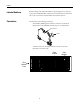
Chapter 3 Operation of Plotter Chapter Objectives This chapter covers: • Operation • ON/OFF Buttons • Clear Buffer • Pen Station Open/Close Button • Stop/View Button Operation Once you have installed the plotter and connected the power supply and data cable, you may switch the potter on. IMPORTANT Before switching the device on, please ensure there are no objects on the writing/plotting area which might prevent the writing arm from moving freely.
3-2 Operation of Plotter stop mode is entered by pressing the “Stop” button. Then delete the data by pressing the “Clear Buffer” button. Pen Station Open/Close Button Pressing the “Pen Station Open/Close” button will operate the pen station. A pen must be installed in the bottom location prior to plotting (unless ClearTools software has pen selection set to “no,” in which case the pen must be installed manually in the plotter arm).
Operation of Plotter 3-3 Cursor and Pen Up/Down Buttons The “Cursor” buttons are used to move the writing arm manually in all directions. The “Pen Up/Down” buttons lowers and raises the plotter pen. To raise or lower the pen, the system must be in the stop mode. IMPORTANT These key functions are not used for normal operation. They are intended solely for service functions. Open the pen station before using the plotter.
3-4 Operation of Plotter Notes:
Chapter 4 Troubleshooting and Maintenance Chapter Objectives This chapter describes how to: Troubleshoot the marking system Perform routine maintenance Clean the plotter pens Technical Specifications Using the Troubleshooting Chart Table 4.A is a troubleshooting chart. This chart lists the most common operating problems, probable causes, and steps to correct the problem.
4-2 Troubleshooting and Maintenance Table 4.A Troubleshooting Chart Problem Probable Cause(s) Corrective Action(s) Plotter does not power up. 1. Plotter not plugged in. 2. Improper connection to power source. 1. Verify that plotter is plugged in. 2. Verify 110/220 VAC, 50/60 Hz voltage at power source. No communications between plotter and computer. 1. Faulty communications cable. 2. Wrong COM or USB port selected. 3. USB plugged in upside down. 1. Check cable connections. 2.
Troubleshooting and Maintenance 4-3 Removing Sealing Unit from Pen Station 1. Open pen station by pressing the “Open/Close” button. 2. Apply the key (enclosed in the 1492-PLOTSERV) to the sealing unit and carefully lift the sealing unit from the holding device. Inserting and Adjusting Sealing Unit 1. Insert new sealing unit into pen station. 2. Carefully press the sealing unit up to the limit-stop in the aluminium tube. 3.
4-4 Troubleshooting and Maintenance Technical Specifications Table 4.B Technical Specifications Plotter type Flatbed plotter Maximum plotting area 440 mm x 305 mm (17.3 in x 12 in) Plotting speed Max. 40 cm/sec. (15.75 in/sec) Plotter pen 1492-PLOTPEN25, 1492-PLOTPEN35 Ports USB level 1.1 Control language Based on HP-GL 7475A Buffer 16 MB Drive Two-phase step motor Pen station Max. four plotter pens with double seal Addressable resolution 0.01 mm (0.0004 in) Repeat accuracy 0.
Appendix A Appendix A For Plotter Plates with Adhesive Strips, 1492-PLOTPLT, Series A Adhesive Strip Preparation Before placing any markers on the base plate, carefully remove the five green protective coverings from the adhesive strips on the plate. This reveals an adhesive surface which aids in holding a marker card when the plotter is operating. Remove only the green protective covering, not the blue adhesive strip, from the plate.
A-2 Appendix A
Index A Accessories . . . . . . . . . . . . . . . . . . . . . . . . . . . . . . 1-7 Activating the Plotter with ClearTools . . . . . . . 2-20 Adhesive Strip Preparation. . . . . . . . . . . . . . . . . A-1 Marker Types . . . . . . . . . . . . . . . . . . . . . . . . 1-3...1-6 Marker Types, Adjusting . . . . . . . . . . . . . . . . . . .2-24 O ON/OFF Buttons . . . . . . . . . . . . . . . . . . . . . . . . 3-1 Operation . . . . . . . . . . . . . . . . . . . . . . . . . . . . . . . 3-1 B Base Plate . . . .
Index Notes:
Publication1492-UM006D-EN-P — October, 2012 Supersedes Publication1492-UM006C-EN-P — May, 2010 Part Number 41063-289-03 Copyright ©2012 Rockwell Automation, Inc. All Rights Reserved. Printed in USA.