
User guide

(6)
10000021873 (Version 00)
VI. Conversion Module Re-assembly After Fuse Insertion/Replacement (Continued)
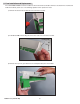
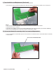
2) Take the module half with the locking tab and partially insert the tab into the mating slot
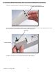
3) At the other end of the module assembly, ensure the bottom guide/retainer clears the top locking extension. Push
the 2 case halves up and in until you here the locking tab snap into place.
4) Replace the module case screw [maximum torque 0.7 Nm (6.9 lb-in)].
Locking Tab: Partially Inserted
Extension
Guide / retainer