
Manual

V. 1492-CM1771-LD002 Conversion Module Specifications
(Operating specifications are when installed in the Conversion System base / cover-plate assembly)
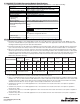
VI. Appendix A - 1771 to 1756 Chassis Conversion System Selection Process
1) Determine the number of 1771 I/O modules used in the 1771 I/O Chassis to be converted to 1756. NOTE: In some
cases two 1756 modules ma
y
be required for one 1771 module. Select the applicable 1492 conversion modules from
t
he Di
g
ital and Analo
g
C
onversion
S
election Table Matrix.
2)
Review the Max Slots for I/O and chassis width data from the below table, and select a 1756 I/O Chassis which meets
y
our conversion needs from Step 1. Ensure the information from the I/O Conversion module tables are reviewed first.
3
)
O
nce the 1756
C
hassis is selected, select the
C
onversion Assembl
y
. The
C
onversion Assembl
y
has the same dimen
-
s
ional foot-print as the 1771 chassis and can use the same mountin
g
hardware. The assembly consists of a base-plate
t
o
h
o
ld
t
h
e convers
i
on mo
d
u
l
es an
d
a cover-
pl
ate to
p
rotect t
h
e mo
d
u
l
es an
d
to mount t
h
e se
l
ecte
d
1756 c
h
ass
i
s.
Th
e
combined depth of the conversion assembl
y
with the 1756 chassis mounted is 10.25 inches (
C
ontroller w
/
ke
y
) to
10.0 inches (Controller w/o Key).
F
oo
t N
o
t
es
:
1771-A3B is not listed as it is used for 19 inch wide instrumentation
p
anels
Two 1771 width dimensions are provided as some PL
C
-5 processors have integrated power supplies. Dimension w
/
P
S
i
ncludes -P1
,
-P2
,
etc. Notice that the width dimension o
f
some 1756 chassis exceed the width o
f
the 1771 chassis with
o
r without the power supply. Cover-plate chassis mounting design allows the excess 1756 chassis width to be evenly
d
istributed to both sides, or excess to right or left.
C
arefully consider this in the conversion
1756-A4 may work in a 1771-A1B application if 4 or less I
/O
slots were used.
C
onversion cover-plate is capable to
mount -A4 or -A
7
1756-A7 ma
y
work in a 1771-A2B application if 6 or less I
/O
slots were used.
C
onversion cover-plate is capable to
mount -A7 or -A10
1756-A10 may work in a 1771-A3B1 application if 10 or less I/O slots were used. Conversion cover-plate is capable to
mount -
A
10 or -
A
13
1756-A13 may work in a 1771-A4B application if 13 or less I
/O
slots were used.
C
onversion cover-plate is capable to
mount -A1
3
or -A17
PN-40373
DIR 10000060085 (Version 00)
Printed in U.S.A.
Max Slots for I/O
4
-A1B w/o
PS
4
-A1B
w/PS
36 8 8
6
912
-A13
(5)
12
-A3B1-A10-A7
(4)
-A2B
w/PS
-A2B w/o
PS
-A7-A4
(3)
16
-A17
(6)
16
-A4B
Chassis Width
(2)
Conversion Assembly
Chassis Parameter(1)
1756 Equivalent
Chassis
1756 Equivalent
Chassis
24.01 29.0623.1519.0119.029.01
12.61 10.35 14.49 14.4914.01 17.61
1771 Chassis
1771 Chassis
1771 Chassis
1492-MUA1B-A4-A7 1492-MUA2B-A7-A10 1492-MUA3-A10-A13 1492-MUA4-A13-A17
1771 Chassis
1756 Equivalent
Chassis
1756 Equivalent
Chassis
Specification
Dimensions
Approximate Shipping Weight
11.81 in. (height) x 4.38 in. (depth) x1.5 in. (width)
300 mm. (height) x 111.25 mm (depth) x 38.1 mm (width)
262.4 g (0.58 lbs) (includes carton)
Storage Temperature -40 to +85°C (-40 to +185°F)
Operating Temperature
0 to 60°C (32 to 140°F)
Operating Humidity
5 to 95% at 60°C (non-condensing)
Shock
Non
-
operating
Operating
50g
30g
Operating Vibration
2g at 10 to 500Hz (Agrees with 1756 I/O module specifications)
Maximum Operating Voltage
240 Vac at 47 to 63Hz or 240 Vdc
Max. Module Operating Current
Per Point:
Per Module:
2 Amps
2 Amps
Agency Certifications
UL Classified: Under UL File Number E113724
CSA
CE: compliant for all applicable directives
Pollution Degree
2
Environmental Rating
IP20
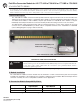
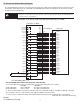
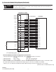
Refer to the Wiring Diagram(s) for
current limits for a specific configuration.
NOTICE
Value