
Manual

30 Rockwell Automation Publication ICM-UM004C-EN-E - February 2014
Chapter 1 Installation
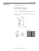
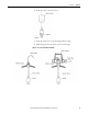
Adjust the Gap
Adjust the gap by using the following procedures.
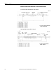
1. Refer to Standard Static Characteristics on page 41
, and prepare a gap gage
matching the gap to produce the desired characteristics.
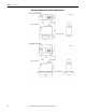
Consider the following items for the gap:
• Set the gap so that even when the target is at the nearest point to the
sensor, the target does not come into direct contact with the sensor.
• Set the gap so that it does not go beyond the linear range of the
connection monitor.
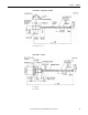
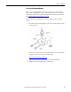
2. Being careful not to scratch the sensor top and target surface, insert the gap
gage between the sensor top and target.
3. Adjust the sensor to a position where the gap gage just moves freely, and
affix in place with the jam nut.
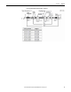
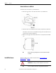
4. Tighten the jam nut with the following torque.
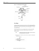
TIP
After completing all wiring connections, you can perform gap adjustment
by using a tester.
Make sure to fully understand the content described in this chapter and
complete all connection work, then perform the gap adjustment by using
the Set Gap Voltage
procedures on page 35.
Table 2 - Torque Requirements
Sensor Example
Tightening Torque
N•m kgf-cm lb•in
1442-PS-05xxM (5 mm metric) 1442-PS-0503M0010N 4 41 35.4
1442-PS-05xxE (5 mm English) 1442-PS-0512E0010N 1.4 15 12.4
1442-PS-08xxM (8 mm metric) 1442-PS-0803M0010N 8.5 87 75.2
1442-PS-08xxE (8 mm English) 1442-PS-0812E0010N 6.8 69 60.2
1442-PS-11xxM (11 mm metric) 1442-PS-1104M0510N 26.1 266 231
1442-PS-11xxE (11 mm English) 1442-PS-1116E0510N 18.6 190 164
1442-PS-18xxM (18 mm metric) 1442-PS-1805M0510A 58.8 600 520