User Manual 1442 Eddy Current Probe System
Important User Information Read this document and the documents listed in the additional resources section about installation, configuration, and operation of this equipment before you install, configure, operate, or maintain this product. Users are required to familiarize themselves with installation and wiring instructions in addition to requirements of all applicable codes, laws, and standards.
Summary of Changes This manual contains new and updated information. Changes throughout this revision are marked by change bars, as shown to the right of this paragraph. New and Updated Information Temperature ranges and wire sizes were corrected as appropriate in this manual.
Summary of Changes Notes: 4 Rockwell Automation Publication ICM-UM004C-EN-E - February 2014
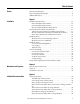
Table of Contents Preface Measurement Principles . . . . . . . . . . . . . . . . . . . . . . . . . . . . . . . . . . . . . . . . . . . . 7 System Configuration Example. . . . . . . . . . . . . . . . . . . . . . . . . . . . . . . . . . . . . . 8 Additional Resources . . . . . . . . . . . . . . . . . . . . . . . . . . . . . . . . . . . . . . . . . . . . . . . 9 Chapter 1 Installation Installation Environment . . . . . . . . . . . . . . . . . . . . . . . . . . . . . . . . . . . . . . . . .
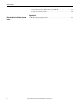
Table of Contents Static Characteristic Effect Due to Side Wall. . . . . . . . . . . . . . . . . . . . 49 Frequency Characteristics . . . . . . . . . . . . . . . . . . . . . . . . . . . . . . . . . . . . . 50 Appendix A Wire the Unit to a Monitor System Index 6 Cable Wiring/Laying Examples. . . . . . . . . . . . . . . . . . . . . . . . . . . . . . . . . . . .
Preface This manual describes how to install and use the 1442 Series Eddy Current Probe System. The 1442 Series eddy current probe system performs non-contact measurement of the distance between the sensor and the measured object (target), and outputs a proportional voltage signal. The static component of the measurement is the "gap," the absolute (DC) distance from the target surface to the probe tip.
Preface You can find the gap between the sensor and the target by measuring the sensor impedance if the following relationships are identified: • Relationship between the sensor and the target gap. • Relationship of the sensor impedance. This system is designed to fulfill the specifications when used under the following configuration. System Configuration Example IMPORTANT Always combine the components of this system (sensor, extension cable, and driver) to configure it as follows.
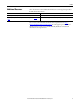
Preface Additional Resources These documents contain additional information concerning related products from Rockwell Automation. Resource Description 1442 Eddy Current Probe Systems Specifications Technical Data, publication 1442-TD001. Provides specifications for the 1442 Eddy Current Probe System. Turbine Supervisory Instrumentation System Selection Guide, publication GMSI10SG002. Provides details to help you choose a Turbine Supervisory Instrumentation system.
Preface Notes: 10 Rockwell Automation Publication ICM-UM004C-EN-E - February 2014
Chapter 1 Installation This chapter describes how to install a 1442 Series Eddy Current Probe System. ATTENTION: Always ground the system. Never apply power until all wiring work and connection work has been completed. If this is not followed, there is a possibility of electrocution. Installation work, wiring, and connections must be performed by a person with knowledge in instrumentation.
Chapter 1 Installation Installation Environment Driver Installation Environment Install the driver in a location that satisfies the following environmental and installation conditions. Environmental Conditions Feature Specification Ambient temperature Must be in a range of -30…80 °C (-22…176 °F) when devices are operating. Ambient humidity Must be in a range of 30…95% RH (noncondensing) when devices are operating. Vibration condition Must be 10 m/s2 (1 g) or less at 10…150 Hz.
Installation Chapter 1 • Do not locate above heat emitting objects. Sensor Installation Environment Install the sensor at a location that satisfies the following environmental and installation conditions. Environmental Conditions Feature Specification Ambient temperature ATEX applications must be in a range of -35…80 °C (-31…176 °F) when devices are operating. CSA applications must be in a range of -35…85 °C (-31…185 °F) when devices are operating.
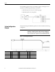
Chapter 1 Installation • When placing other sensors next to each other, separate the sensor tops by not less than 10 times the sensor tip diameter to prevent interference. 40 mm (1.57 in.) or more 40 mm (1.57 in.) or more • The sensor must be installed on a surface with adequate rigidity that is not affected by an outside vibration. If the sensor vibrates, an accurate measurement cannot be taken. • For shapes and dimensions around the sensor, refer to the installation examples (1…3) below.
Installation Chapter 1 Table 1 - Installation Examples Example Description Example 4 If dimension X is less than 1.2 times the tip diameter, the measurement will be affected by the attachment plate. Example 5 If dimension Y is less than 3 times the tip diameter, the measurement will be affected by the attachment plate. Example 6 If the attachment plate around the sensor top is chamfered, it will be affected by the attachment plate.
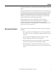
Chapter 1 Installation The characteristics of output (V) and gap (mm) are as shown in the graph below. Speed Measurements Assumes measurements are made with a 5 mm or 8 mm probe. Figure 2 - Dimension of target (recommended for rotational speed measurement): BA D D A C C Recommended dimension of target (mm) Recommended set gap (mm) 16 D mm mils A≥6 A ≥ 236 B≥7 B ≥ 275 C ≥ 2.5 C ≥ 98 D ≥ 15 D ≥ 590 1.0...1.5 39...
Installation Chapter 1 Extension Cable Installation Environment Install the extension cable in a location that satisfies the following environmental and installation conditions. Outer Dimensions and Part Nomenclature Feature Specification Ambient temperature Cable must be in a range of -35…177 °C (-31…350 °F) when devices are operating. Connector must be in a range of -35…125 °C (-31…257 °F) when devices are operating.
Chapter 1 Installation 8 mm Sensor L1 = Unthreaded length L2 = Case length L3 = Cable length Reverse 8 mm Sensor L3 = Cable length 18 Rockwell Automation Publication ICM-UM004C-EN-E - February 2014
Installation Chapter 1 11 mm Probes - Non Armored L1 = Unthreaded length L2 = Body length L3 = Cable length 11 mm Probes - Armored L1 = Unthreaded length L2 = Body length L3 = Cable length Rockwell Automation Publication ICM-UM004C-EN-E - February 2014 19
Chapter 1 Installation 18 mm Probes - Armored L1 = Unthreaded length L2 = Body length L3 = Cable length 25 mm Probes - Armored L1 = Unthreaded length L2 = Body length L3 = Cable length 20 Rockwell Automation Publication ICM-UM004C-EN-E - February 2014
Installation Chapter 1 25 mm Probes - Flange Mount, Armored 2 = 4 holes in flange, 14 mm deep with M6 threads L3 = Cable length, +30% / -0% 50 mm Probes - Armored L2 = Body length L3 = Cable length Rockwell Automation Publication ICM-UM004C-EN-E - February 2014 21
Chapter 1 Installation Extension Cable Outer Dimensions and Part Nomenclature 5, 8, and 11 mm Probe Extension Cables - Non Armored 5 and 8 mm Probe Extension Cables - Armored 22 Rockwell Automation Publication ICM-UM004C-EN-E - February 2014
Installation Chapter 1 11 mm to 50 mm Probe Extension Cables - Armored Rockwell Automation Publication ICM-UM004C-EN-E - February 2014 23
Chapter 1 Installation Driver Outer Dimensions and Part Nomenclature 24 Rockwell Automation Publication ICM-UM004C-EN-E - February 2014
Installation Install the Driver Chapter 1 The driver can be installed on a DIN rail, or it can be mounted on a panel or wall by using the provided adapter. Mount the Driver on the Housing or Panel The driver can be directly mounted on the panel. TIP When attaching to panels or mounts, make sure the surface is strong and flat. Attach the driver to the panel mounting plate and affix with the provided four screws (M4 x 12 mm).
Chapter 1 Installation Mount the Driver to a DIN Rail The driver can be mounted to a 35 mm DIN rail. 1. Hook the upper tabs on the back of the driver onto the DIN rail. 2. Push the driver into the DIN rail until a click is heard from the slide lock. If the driver does not fit onto the DIN rail well, pull on the slide lock and push the driver against the DIN rail. 3. Make sure the upper tabs and the slide lock are securely fixed on the DIN rail.
Installation Chapter 1 Use a Sensor Mounting Bracket If you need a mounting bracket for the sensor, construct your own mounting bracket. The mounting bracket can be readily machined at your site. The bracket must provide a stable, secure, platform that satisfies the conditions described in the Sensor Installation Environment on page 13. When using a sensor mounting bracket, use the following steps to install the sensor. 1.
Chapter 1 Installation Figure 3 - Sensor Mounting Bracket Installation Example Use a Stinger 1442 Series 8-mm reverse-mount probes can be used with commonly available probe holders. Stingers (also known as sensor sleeve), are provided with the probe holder. Stingers can also be purchased from probe holder suppliers or can often be machined locally. The following instruction is a general guide based on common probe holder designs.
Installation Chapter 1 2. Attach the sensor to the sensor sleeve. 3. Attach the sensor sleeve to the mounting (machine casing). 4. Adjust the gap between the sensor top face and the target.
Chapter 1 Installation Adjust the Gap Adjust the gap by using the following procedures. TIP After completing all wiring connections, you can perform gap adjustment by using a tester. Make sure to fully understand the content described in this chapter and complete all connection work, then perform the gap adjustment by using the Set Gap Voltage procedures on page 35. 1. Refer to Standard Static Characteristics on page 41, and prepare a gap gage matching the gap to produce the desired characteristics.
Installation Chapter 1 Table 2 - Torque Requirements Tightening Torque Sensor Example N•m kgf-cm lb•in 1442-PS-18xxE (18 mm English) 1442-PS-1820E0510A 88.2 900 780 1442-PS-25xxM (25 mm metric) 1442-PS-2505M0510A 176 1800 1557 1442-PS-25xxE (25 mm English) 1442-PS-2520E0510A 196 2000 1734 1442-PS-50xxM (50 mm metric) 1442-PS-5005M0010A 176 1800 1557 1442-PS-50xxE (50 mm English) 1442-PS-5020E0010A 196 2000 1734 1442-PR-08xxM (8 mm rev mnt metric) 1442-PR-0803M0505N 8.
Chapter 1 Installation This section describes the wiring connections for the 1442 Series Eddy Current Probe system. Connect the Wiring The 1442 Series includes color–coded bands on the ends of each component. The color–coded bands help you identify the length of the extension cable and the length of the probe so that the total system length (5 or 9 meters) can be matched to the appropriate driver. When the system is properly "sized," the color bands for the probe, extension cable, and driver will match.
Installation Chapter 1 Connections are performed in the following order. 1. Connect the extension cable (when using the extension cable). 2. Connect the sensor. 3. Connect the XM® module. 4. Verify the connections. 5. Check the gap voltage. Connect the Extension Cable Use the following steps to connect the sensor and extension cable. TIP The connection area of the connector must not be exposed to water or oil.
Chapter 1 Installation 4. Cover the insulation sleeve over the connector. 5. Apply hot air on the insulation sleeve to shrink the insulation sleeve. ATTENTION: Never use vinyl tape to insulate. • During extended periods of use or when the connecter temperature exceeds 80 °C (176 °F), vinyl electrical tape can harden or the adhesive can deteriorate, leading to a dirty connector and faulty insulation. • If there is not a spare insulation sleeve available, protect the connector with a fluorine resin tape.
Installation Chapter 1 Connect the Module The 1442 sensors can be connected to many different Allen-Bradley 1440 XM Series or 1444 Dynamix® Series modules. Refer to the appropriate Module User Manual for wiring requirements and instructions on how to wire the sensor to the module. Verify the Connections Before turning on the power, verify the following connections: · Be sure that there are no loose terminals, and that all wiring is properly connected.
Chapter 1 Installation Warm-up is necessary to collect accurate data. 3. Connect the tester (voltmeter) across the Input Signal and Input Common terminals on the measurement module base and read the voltage. 4. Refer to Standard Static Characteristics on page 41 to make sure that the desired set gap voltage is indicate IMPORTANT Data indicated in Standard Static Characteristics (on page 41) are measured for a SCM440 flat target (diameter more than 33 mm).
Installation Chapter 1 c. After adjustment, tighten the sensor jam nut to the specified torque value (see table on page 30). ATTENTION: Always tighten the lock nut at the specified torque. TIP Recommended Specifications for the Monitor Cable The measurement precision described in the specifications will be satisfied approximately five minutes after turning on the power. Use a commercially sold cable to connect the probe driver to the monitor.
Chapter 1 Installation Notes: 38 Rockwell Automation Publication ICM-UM004C-EN-E - February 2014
Chapter 2 Maintenance and Inspection This chapter describes the maintenance and inspection procedures for the unit. Periodic Inspection Intervals To maintain performance and secure system stability of the unit, inspect the system and its mounts for corrosion, properly-tightened or torqued fittings and connections, and component conditions annually. Check sensor gap settings annually and at any time measurements become suspect. Refer to Set Gap Voltage on page 36.
Chapter 2 Maintenance and Inspection Troubleshoot the Unit Use the table below to troubleshoot problems with the unit. Symptom Possible Cause Output is 0V DC and does not change. Power is not on. Turn on the power. Unit is not connected properly. Refer to Connect the Wiring on page 32 to make sure the unit is wired correctly. The driver is faulty. Replace the driver. The target is beyond the measurement range. Refer to Set Gap Voltage on page 36 to adjust the gap.
Chapter 3 Individual Characteristic Data Characteristic Data This chapter describes static characteristics, temperature characteristics, and other characteristic data. Use this data to determine the gap. Standard Static Characteristics Target material is SCM440 flat face (diameter 15 mm or more).
Chapter 3 Individual Characteristic Data Sensor Temperature Characteristics System cable length is 5 m.
Individual Characteristic Data Chapter 3 Driver Temperature Characteristics System cable length is 5 m.
Chapter 3 Individual Characteristic Data Static Characteristic Effect Due to Power Source Voltage Variation 44 Rockwell Automation Publication ICM-UM004C-EN-E - February 2014
Individual Characteristic Data Chapter 3 Static Characteristic Effect by Target Material Rockwell Automation Publication ICM-UM004C-EN-E - February 2014 45
Chapter 3 Individual Characteristic Data Static Characteristic Effect Due to Target Diameter Target material is SCM440.
Individual Characteristic Data Chapter 3 Static Effect by Target Curved Surface Target material is SCM440.
Chapter 3 Individual Characteristic Data Static Characteristic Effect Due to Target End Face Target material is SCM440.
Individual Characteristic Data Chapter 3 Static Characteristic Effect Due to Side Wall Target and side wall material is SCM440.
Chapter 3 Individual Characteristic Data Frequency Characteristics 50 Rockwell Automation Publication ICM-UM004C-EN-E - February 2014
Appendix A Wire the Unit to a Monitor System The 1442 Series Probe System is designed to satisfy the API-670 standard. Any monitor designed to connect API-670 probes can be used with these sensors. Consider the following recommendations when wiring the probe driver to a monitor: · Use a good quality instrumentation cable with three-conductor stranded wire and shield. – Wire must be rated with a maximum capacitance of 60 pF/ft (197 pF/m) and inductance of 0.3 μH/ft (1 μH/m).
Appendix A Wire the Unit to a Monitor System Cable Wiring/Laying Examples Good Example 52 The following illustrations provide examples on how to wire and lay the cable.
Index Numerics 1442 driver dimensions 24 installation 25 installation environment 12 1442 extension cable connecting 33 dimensions 22 1442 reverse mount probe dimensions 18, 19, 20, 21 1442 Sensors connecting 34 dimensions 17 installation environment 13 C cable wiring 51 examples 51 issues 51 characteristic data 41 D dimensions 17 din rail mounting 26 driver installation 25 din rail mounting 26 housing mounting 25 panel mounting 25 driver installation environment 12 P panel mounting 25 S sensor installa
Index 54 Rockwell Automation Publication ICM-UM004C-EN-E - February 2014
Rockwell Automation Support Rockwell Automation provides technical information on the Web to assist you in using its products. At http://www.rockwellautomation.com/support you can find technical and application notes, sample code, and links to software service packs. You can also visit our Support Center at https://rockwellautomation.custhelp.com/ for software updates, support chats and forums, technical information, FAQs, and to sign up for product notification updates.