
Owner manual

86 Rockwell Automation Publication GMSI10-UM002D-EN-E - August 2012
Chapter 2 Setting Up Measurements
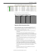
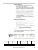
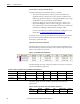
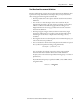
The following table shows the transducer specifications in the collection
specifications
.
Spectrum Measurement Definitions
Emonitor and the Enpac 2500 support spectrum measurement definitions. This
topic lists the unique characteristics of the Enpac 2500 that you may need to
know when setting up and collecting spectrum data.
• The Enpac cannot collect phase with a spectrum measurement definition.
In other words, do NOT check the Also collect phase data checkbox in the
Collection Specification dialog.
• You can choose to have the Enpac 2500 collect a spectrum only if a
magnitude measurement at the same location is in alarm. Set the Collect
and store condition in the Edit Storage Specification dialog to ‘On
Magnitude Alarm’ for the storage specification for the spectrum
measurement definition.
Time Synchronous Averaging in the Enpac 2500 Data Collector
• Time synchronous averaging cancels out the effects of signals not related
to the synchronizing trigger. Time synchronous mechanical effects include
imbalance, misalignment, eccentricity of bent shafts, blade passing, and
gear meshing.
• Time synchronous averaging requires the internal laser tachometer or
external trigger.
• Set up a Collection Specification with the averaging Type set to ‘Time
Synchronous’ and enter the Number of averages. Use a large number of
averages (such as 20 or 30) to get the desired reduction in non-
synchronous effects.
For more on supported averaging in the Enpac 2500, see
Number and
Type of Averages on page 74.
Table 24 - Transducer Specifications in Numeric Collection Specifications
Name Base Unit Input Type Units Calibration Value
(1)
(1) Make sure you enter the Calibration value that converts the voltage to a known unit such as speed.
DC Offset
Temperature Temperature DC Coupled deg. F See note below. 0
Tachometer Frequency DC Coupled RPM See note below. 0
Manual Entry None Manual Entry None See note below. 0