
Owner manual

Rockwell Automation Publication GMSI10-UM002D-EN-E - August 2012 197
Bump Test Application Chapter 7
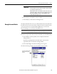
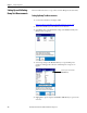
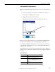
6. Select the choice by pressing the arrow keys or type in a value using the
numeric key pad.
7. Press the LEFT ARROW key to save your selections.
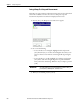
8. Press F3 (Save) to save the current settings to a file.
Refer to
Saving a Bump Test Setup and Measurement on page 200.
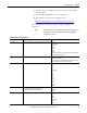
Use the descriptions in this table to help you configure the Bump Test
parameters..
TIP
For the bump test, some of the vibration measurement settings are pre-set
to simplify your setup. The FFT window is pre-set to Hanning and the
Overlap is pre-set to 50%.
Table 40 - Bump Test Setup Parameters
Parameter name Description Values/Comments
Sensor Type Sets the type of vibration measurement to be used in data collection. Options:
Accel G (default)
Accel m/s
2
Vel IPS
Vel mm/s
Disp um
Disp mil
Your selection determines the available options and engineering units
for subsequent setup parameters.
Sens. (mV/EU) The transducer sensitivity in millivolts (mV) per engineering unit (EU). 1…2000 mV/EU
Default value is 50 mV/EU
The sensitivity value is included with the transducers documentation
or it may be imprinted on the side of the transducer.
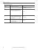
Range (EU) The expected maximum amplitude range value. Options:
.1 EU
.2 EU
.5 EU
1 EU (default)
2 EU
5 EU
10 EU
20 EU
50 EU
100 EU
200 EU
500 EU
1000 EU
2000 EU
X-axis units Set the x-axis frequency units for displaying spectra/FFT data.
• Hz - Displays spectra in Hertz, cycles per second.
• CPM - Displays spectra in cycles per minute.
Options:
Hz (default)
CPM
Filter Sets the high pass filter to be used in data collection. Options:
Off
.36 Hz
1.1 Hz
2 Hz (default)
10 Hz
70 Hz