
Instruction Manual


16 Rockwell Automation Publication 1441-UM006A-EN-P - May 2011
Chapter 2 Run Up/Coast Down Extension Module
The application acquires a simultaneous noise or vibration signal and a
tachometer signal.
This example setup includes the following:
• Accelerometer attached to connector A of the Dynamix 2500 data
collector
• Optical tachometer signal connected to the POWER/USB/TRIGGER
cable
• Tripod for tachometer signal stability
• Speed reference trigger
• Small piece of reflective tape on the part of the shaft can serve as a reference
trigger or you can simply pass the laser over a notch in the shaft
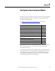
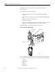
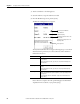
This graphic illustrates a typical Run Up/Coast Down setup.
Figure 1 - Run Up/Coast Down Setup
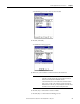
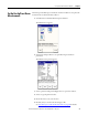
The recorded data is saved in the form of a Microsoft .wav time waveform file.
You can analyze this file and viewed in a variety of different formats including:
•Bode Plot
•Nyquist Plot
• Table
•Waterfall
•Spectrogram
32147-M
Accelerometer
Tripod
Tachometer
Reflective Tape