User Manual Bump Test Extension Module for the Dynamix 2500 Data Collector Catalog Number 1441-DYN25-MBMP
Important User Information Solid-state equipment has operational characteristics differing from those of electromechanical equipment. Safety Guidelines for the Application, Installation and Maintenance of Solid State Controls (publication SGI-1.1 available from your local Rockwell Automation sales office or online at http://www.rockwellautomation.com/literature/) describes some important differences between solid-state equipment and hard-wired electromechanical devices.
Table of Contents Preface Optional Extension Modules. . . . . . . . . . . . . . . . . . . . . . . . . . . . . . . . . . . . . . . . 5 Additional Resources . . . . . . . . . . . . . . . . . . . . . . . . . . . . . . . . . . . . . . . . . . . . . . . 6 Chapter 1 Installing Optional Extension Modules Install Extension Modules . . . . . . . . . . . . . . . . . . . . . . . . . . . . . . . . . . . . . . . . . . 7 Uninstall Extension Modules. . . . . . . . . . . . . . . . . . . . . . . . . . . . . . . . . . . .
Table of Contents Notes: 4 Rockwell Automation Publication 1441-UM002A-EN-P - May 2011
Preface This manual describes the Bump Test and how to apply it using the Dynamix 2500 data collector. You install the extension module with the Bump Test Secure Digital (SD) card. See Installing Optional Extension Modules on page 7 for installation instructions. When using the Dynamix 2500 data collector and the Bump Test extension module, you can do the following: • Determine natural (or resonant) frequencies of a machine or structure. • Identify a structure’s resonant modes.
Preface Additional Resources These documents contain additional information concerning related products from Rockwell Automation. Resource Description Dynamix 2500 Data Collector User Manual, publication 1441-UM001 Describes the Dynamix 2500 data collector, which provides predictive maintenance by using noise and vibration analysis.
Chapter 1 Installing Optional Extension Modules The data collector uses the Extension Manager to install and uninstall extension modules. These extension modules are licensed and ordered separately from the basic entry-level product.
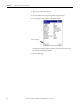
Chapter 1 Installing Optional Extension Modules 4. Apply power to the data collector. 5. From the Main menu, choose Setup Utility and press Enter. 6. Press 0 (Shift) to display the second set of functions. Extension Manager The Extension Manager function remains on the screen for about three seconds after releasing the 0 (Shift). 7. Press F1 (Extn Mgr).
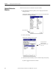
Installing Optional Extension Modules Chapter 1 The Extension Manager screen appears, showing the current extension module installations. 8. Press 0 (Shift) to display the Install Extension function. 9. Press F2 (Install) to install the new extension module. When the installation is complete, a confirmation prompt appears. 10. Press F4 (OK). The new extension module appears in the list. 11. Press F4 (Esc) to exit the Extension Manager screen.
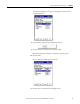
Chapter 1 Installing Optional Extension Modules Uninstall Extension Modules Follow these instructions to uninstall an extension module. 1. Press 0 (Shift) from the Setup Utility screen to display the Extension Manager function. The Extension Manager function remains on the screen for about three seconds after releasing the 0 (Shift). Extension Manager 2. Press F1 (Extn Mgr). The Extension Manager screen appears. This screen lists the extension modules currently installed and the on the unit. 3.
Installing Optional Extension Modules Chapter 1 A checkmark appears next to that extension module. 4. Press F1 (Uninstall). A confirmation message appears. 5. Make sure your installation card is inserted into the instrument. IMPORTANT The extension module is uninstalled and the license on the card is released so that the card can be used to install the extension module on another Dynamix 2500 data collector.
Chapter 1 Installing Optional Extension Modules Manage Extension Modules The Dynamix 2500 data collector lets you hide installed extension modules from the Main Menu. You may need to hide an advanced extension module icon, for example, RUCD and FRF, from an inexperienced user. IMPORTANT Once an extension module is hidden, its icon is not represented on the Main Menu or displayed in the Dynamix 2500 data collector About screen.
Installing Optional Extension Modules Chapter 1 3. Select the extension module that you want to hide or show and press F2 (Show/Hide). TIP If you want to show or hide multiple extension modules simultaneously, select each extension module and press F3 (Select). A checkbox appears next to each selected extension module. If you select multiple extension modules and some are hidden while others are shown, F2 (Show/Hide) reflects the status of the selected extension module. 4.
Chapter 1 Installing Optional Extension Modules Notes: 14 Rockwell Automation Publication 1441-UM002A-EN-P - May 2011
Chapter 2 Bump Test Extension Module The Bump Test extension module is an optional module for the Dynamix 2500 data collector. You install the extension module with the Bump Test SD storage card. See Installing Optional Extension Modules on page 7 for installation instructions.
Chapter 2 Bump Test Extension Module Set Up Bump Test Measurements Follow these steps to configure the parameters for the measurement. 1. Connect the transducer to the Dynamix 2500 data collector. 2. Attach the transducer to the machine case or structure. 3. Select Bump Test on the Main Menu and press Enter. The Bump Test screen appears. • Setup displays the Bump Test setup parameters and begins data collection.
Bump Test Extension Module Chapter 2 See Bump Test Parameter Descriptions on page 17 for complete descriptions of the parameters. 5. Configure the Bump Test setup parameters. Table 2 - Bump Test Parameter Descriptions Parameter Description Value Num. Channels Number of Channels you are using in the Bump Test. 1 (X) 2 (X and Y) 3 (X, Y, and Z) 4 (X, Y, Z, R) Sensor Type Specifies the type of sensor used (typically Accel G).
Chapter 2 Bump Test Extension Module Table 2 - Bump Test Parameter Descriptions Parameter Description Value Lines Specify the measurement lines of resolution. 400 (default) The increased resolution requires increased time for data collection and consumes more storage memory. Avg. Type 100, 200, 400, 800, 1600, 3200, 6400, 12800, 25600 Specify the Peak Hold averaging. Pk Hold The data collector holds the highest spectral peak for each hammer hit.
Bump Test Extension Module Collect Bump Test Measurements Chapter 2 After setting up the parameters, you are ready to collect Bump Test data. 1. Press F3 (Start) to collect data. The Bump Test-Taking Data screen appears. 2. Using an impacting device, hit the machine. Notice the natural frequency spectral peaks displayed on the screen. 3. Commence bump test hammer hits to display natural frequency spectral peaks. 4. Move the cursors to identify natural frequencies.
Chapter 2 Bump Test Extension Module Peak Find cursor Harmonic cursor • Press P (7) to move the cursor to the next significant peak. • Press H (4) to display the harmonic cursors. Each time you press H, it toggles through the functions. Table 3 - Significant Peak Functions Save a Bump Test Setup and Measurement On pressing H Function Once Enables the harmonic cursors. Press the Left and Right arrows to move the harmonic cursors. Twice The cursor line is displayed with the harmonic cursors.
Bump Test Extension Module Chapter 2 3. Select save reading as and press F3 (Save). 4. Enter a file name by using the keypad or accept the default file name (current date timestamp). If you want to overwrite an existing file, select the file and press F3 (Save) and you will have the option to replace the file with the new one, such as adding the machine name in front of the timestamp. 5. When the entry is complete, press F2 (OK).
Chapter 2 Bump Test Extension Module The Bump Test screen appears. 4. Select Recall and press Enter. The Bump Test - Load Setup screen appears. 5. Select the filename (test settings) that you want to recall (reload) and press F3 (Open). The Bump Test - Setup screen appears. 6. You can edit the settings or start collecting more data. See Set Up Bump Test Measurements on page 16.
Bump Test Extension Module Review Bump Test Measurements Chapter 2 You can review previously recorded measurements with the Dynamix 2500 data collector. 1. Select Review Data on the Bump Test screen and press Enter. The Bump Test - Review Data screen appears. 2. Select a measurement for review and press F3 (Open). The measurement appears. 3. Press F2 (Prev) and F3 (Next) to display the previous or next measurement. 4. Press F1 (Print) if you what to create a .
Chapter 2 Bump Test Extension Module 5. When finished, press F4 (Back) to return to the Review Data screen to review additional stored measurements. TIP To delete previously saved bump test data, select the file and press 0 (Shift) and then F4 (Delete). 6. Select the file that you want to review and press F3 (Open).
Bump Test Extension Module Save Files to Your Computer Chapter 2 You can save your files to your computer by using the ActiveSync connection. Follow these instructions to back up your data to your computer by using the ActiveSync software. 1. Connect the instrument with the USB cable to your computer. ActiveSync automatically senses the connection and displays the Connected – Synchronized message.
Chapter 2 Bump Test Extension Module Back Up Your files Follow these instructions to back up data to an SD storage card. IMPORTANT The back up option can erase existing files on the SD storage device. It is recommend that a blank SD card is used for backing up your files. The SD storage card should not be disconnected in hazardous areas. It must be connected and disconnected only in a safe area. 1. Insert an SD storage card into the instrument. 2.
Bump Test Extension Module Chapter 2 If a display prompts whether to format the card prior to backup, answer appropriately. IMPORTANT When you answer Yes, all data is deleted. All selected measurement files are copied to the SD card and a Backup Complete message appears. 5. Press F2 (OK) to return to the Review Data screen. 6. Remove the card and store in a safe place.
Chapter 2 Bump Test Extension Module Delete Bump Test Files You can delete a Bump Test measurement or setup from the Dynamix 2500 data collector. 1. Select Review Data (saved measurements) or Recall (saved settings) and press Enter. 2. On the Bump Test - Review Data screen, select a file. When the file is listed on the root of the data collector, it is saved internally. If you want to delete a file on the storage card either open the folder and delete the file or you can use the ActiveSync software.
Bump Test Extension Module Chapter 2 3. Use 0 (Shift) on any Recall screen to display the delete function. 4. Select a file and press 0 (Shift). 5. Press F4 (Delete). The deleting file popup appears. 6. Press F2 (Yes) or F3 (No).
Chapter 2 Bump Test Extension Module Notes: 30 Rockwell Automation Publication 1441-UM002A-EN-P - May 2011
Index Symbols range 17 .
Index Notes: 32 Rockwell Automation Publication 1441-UM002A-EN-P - May 2011
Rockwell Automation Support Rockwell Automation provides technical information on the Web to assist you in using its products. At http://www.rockwellautomation.com/support/, you can find technical manuals, a knowledge base of FAQs, technical and application notes, sample code and links to software service packs, and a MySupport feature that you can customize to make the best use of these tools.