User Manual Balancing Extension Module for the Dynamix 2500 Data Collector Catalog Number 1441-DYN25-MBAL
Important User Information Solid-state equipment has operational characteristics differing from those of electromechanical equipment. Safety Guidelines for the Application, Installation and Maintenance of Solid State Controls (publication SGI-1.1 available from your local Rockwell Automation sales office or online at http://www.rockwellautomation.com/literature/) describes some important differences between solid-state equipment and hard-wired electromechanical devices.
Table of Contents Preface Optional Extension Modules. . . . . . . . . . . . . . . . . . . . . . . . . . . . . . . . . . . . . . . . 5 Additional Resources . . . . . . . . . . . . . . . . . . . . . . . . . . . . . . . . . . . . . . . . . . . . . . . 6 Chapter 1 Installing Optional Extension Modules Install Extension Modules . . . . . . . . . . . . . . . . . . . . . . . . . . . . . . . . . . . . . . . . . . 7 Uninstall Extension Modules. . . . . . . . . . . . . . . . . . . . . . . . . . . . . . . . . . . .
Table of Contents Notes: 4 Rockwell Automation Publication 1441-UM004A-EN-P - May 2011
Preface This manual describes the Balancing extension module for the Dynamix 2500 data collector. You install the extension module with the Balancing Secure Digital (SD) card. See Installing Optional Extension Modules on page 7 for installation instructions. The balancing test determines the amount and location of the heavy spot on a rotating shaft so that you can balance it with an equal amount of weight in the opposite direction.
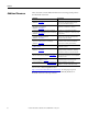
Preface Additional Resources These documents contain additional information concerning related products from Rockwell Automation. Resource Description Dynamix 2500 Data Collector User Manual, publication 1441-UM001 Describes the Dynamix 2500 data collector which provides predictive maintenance by using noise and vibration analysis.
Chapter 1 Installing Optional Extension Modules The data collector uses the Extension Manager to install and uninstall extension modules. These extension modules are licensed and ordered separately from the basic entry-level product.
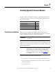
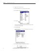
Chapter 3 Installing Optional Extension Modules 4. Apply power to the data collector. 5. From the Main Menu, select Setup Utility and press Enter. 6. Press 0 (Shift) to display the second set of functions. Extension Manager The Extension Manager function remains on the screen for about three seconds after releasing 0 (Shift). 7. Press F1 (Extn Mgr). The Extension Manager screen appears showing the current extension module installations. 8. Press 0 (Shift) to display the Install Extension function. 9.
Installing Optional Extension Modules Chapter 3 When the installation is complete, a confirmation prompt appears. 10. Press F4 (OK). The new extension module appears in the list. 11. Press F4 (Esc) to exit the Extension Manager screen. Uninstall Extension Modules Follow these instructions to uninstall an extension module. 1. Press 0 (Shift) from the Setup Utility screen to display the Extension Manager function.
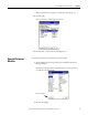
Chapter 3 Installing Optional Extension Modules The Extension Manager screen appears. This screen lists the extension modules currently installed and the on the unit. 3. Select the extension module you want to uninstall and press F3 (Select). F3 (Select) toggles the selection on and off. A checkmark appears next to that extension module. 4. Press F1 (Uninstall).
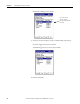
Installing Optional Extension Modules Chapter 3 A confirmation message appears. 5. Make sure your installation card is inserted into the instrument. IMPORTANT The extension module is uninstalled and the license on the card is released so that the card can be used to install the extension module on another Dynamix 2500 data collector.
Chapter 3 Installing Optional Extension Modules Manage Extension Modules The Dynamix 2500 data collector lets you to hide installed extension modules from the Main Menu. You may need to hide an advanced extension module icon from an inexperienced user, for example, RUCD and FRF. IMPORTANT Once an extension module is hidden, its icon is not represented on the Main Menu or displayed in the Dynamix 2500 data collector About screen.
Installing Optional Extension Modules Chapter 3 3. Select the extension module that you want to hide or show and press F2 (Show/Hide). TIP If you want to show or hide multiple extension modules simultaneously, select each extension module and press F3 (Select). A checkbox appears next to each selected extension module. If you select multiple extension modules and some are hidden while others are shown, F2 (Show/Hide) reflects the status of the selected extension module. 4.
Chapter 3 Installing Optional Extension Modules Notes: 14 Rockwell Automation Publication 1441-UM004A-EN-P - May 2011
Chapter 2 Balancing Extension Module The Balancing extension module is an optional module for the Dynamix 2500 data collector. You install the extension module with the Balancing Secure Digital (SD) storage card.
Chapter 2 Balancing Extension Module Balancing Measurements Balancing is the technique for determining the amount and location of the heavy spot on a rotating shaft so that you can balance it with an equal amount of weight in the opposite direction. These methods go through the technique with stopping points where you start and stop the machine to perform weight addition or subtraction.
Balancing Extension Module Chapter 2 2. Perform the initial measurement. a. Start the machine. b. Take the initial measurement. The initial measurement provides a starting place for balancing computations. It records the machine's initial imbalance, 1X vibration magnitude and phase angle. Later in the procedure, initial measurement data is automatically compared with trial (weight) measurement data to calibrate the machine's imbalance. 3. Attach a trial weight. a.
Chapter 2 Balancing Extension Module 7. If additional trim weights are necessary to balance the machine within tolerances, stop the machine and attach the specified trim weights. a. Stop the machine. b. Attach the specified trim weights. c. Take another measurement. 8. Perform a trim measurement. a. Start the machine. b. Take a trim measurement to verify the machine is balanced within tolerances. If not, you can take additional trim measurements.
Balancing Extension Module Chapter 2 Except for the Solution field, all static-couple balancing parameters are identical to two plane balancing settings. If you want to compute three correction weights, select Static-Couple for the Solution parameter on the Balance - Setup screen. See Balance Extension Module Parameters on page 22 for more information about these parameters.
Chapter 2 Balancing Extension Module Set Up the Balancing Parameters All balancing measurement parameters are set up from Balance Setup screen. Follow these steps to go to the Balancing extension module. 1. From the Main Menu, select Balancing and press Enter. The Balance menu displays. These are the Balance menu options: • Setup Access the Balance - Setup screen where you can set up and perform a new balancing run.
Balancing Extension Module Chapter 2 Balance Setup Screen After setting up your balance measuring equipment and marking your tachometer reference point, the next step is to configure balancing measurement parameters for the balancing run sequence. Follow these steps to setup the Balancing parameters. 1. From the Balance main menu, select Setup and press Enter. The Balance Setup lets you configure the balance measurement parameters. 2. Select an option and press the Right arrow to open a list choices. 3.
Chapter 2 Balancing Extension Module Table 2 - Balance Extension Module Parameters Parameter Description Value Num. of Planes Determines whether single-plane or two-plane balancing is required. A good rule-of-thumb is the rotor’s width-to-diameter (W/D) ratio. The W/D ratio is the width (excluding shaft length) of the combine rotors divided by their diameter. The following chart can be used to help determine whether to use one- or two-plane balancing.
Balancing Extension Module Chapter 2 Table 2 - Balance Extension Module Parameters Parameter Description Value Length Units Specifies the units of measurement used for measuring the radius of the weight placement (from the shaft center to the position of the weight). mm You can use this information when you have the data collector to estimate the trial weight for you. m cm inch (default) feet EU Movement Specify your weight angle placement convention, either With Rotation or Against Rotation.
Chapter 2 Balancing Extension Module Table 2 - Balance Extension Module Parameters Parameter Description Value Detection Selects the type of signal detection and scaling for the measurement: Peak: Scaled from RMS as 2 RMS • Peak - The data collector measures the dynamic signal from zero to peak voltage. Use this or the RMS setting for most acceleration and velocity measurements. • Pk-Pk - The data collector measures the dynamic signal from the minimum peak to the maximum peak.
Balancing Extension Module Chapter 2 Table 2 - Balance Extension Module Parameters Parameter Description Value Plane (x) Sets the plane for which the settings below apply. 1 Two plane get two sets of the following attributes/parameters (settings) The input channel required for the measurement. 2 X (default) on connector A only Select channel X for single-plane balancing, with the transducer connected to the data collector’s Connection A.
Chapter 2 Balancing Extension Module Single Plane Balancing The balancing of a machine in one plane is divided into taking these three measurements: • Initial measurement • Trial weight measurement • Residual measurement You must complete the entire procedure until the vibration level has been reduced enough for your needs. See Balancing Measurements on page 16 for more information.
Balancing Extension Module Chapter 2 Take the Initial Vibration Measurement The initial vibration measurement is taken without any added weights on the machine. The initial vibration measurement establishes a reference of how the machine vibrates at each plane without any extra weight added. This vibration is what will be corrected by the correction weight. TIP Skip step 1 if you are using the internal Laser Tachometer as the trigger source. 1.
Chapter 2 Balancing Extension Module The data collection begins as soon as the trigger conditions are satisfied. The Dynamix 2500 data collector automatically measures the speed, vibration, and plane. The values are continually updated on the screen. Running Speed Vibration Magnitude and Phase Phase Angle and Magnitude Diagram IMPORTANT Note the speed reading at the top of the display. For accurate balancing results, it is important to maintain the same speed across all balancing runs.
Balancing Extension Module Chapter 2 Enter the Trial Weight Manually Follow these instructions to manually enter the trial weight you are attaching to the machine. A negative number can be entered if trial weight is removed, instead of added. Trial weights are typically attached at 0° (the trigger reference). Unless you wish the data collector to estimate a trial weight, the Radius entry is not necessary, so long as you position the trial, correction, and trim weights at the same radius. 1.
Chapter 2 Balancing Extension Module You are returned to the Add Trial Weight screen where the estimated trial weight displays in both the Mass and Estimated Mass fields. Estimate the Trial Weight At times, you may want the data collector to calculate the trial weight for you. The Trial Weight Estimate is based on the criteria that the trial run centrifugal force does not exceed 10% of the bearing shaft load.
Balancing Extension Module Chapter 2 5. When the speed, vibration, and phase values are stable, press Enter. The trial weight measurement is complete and the results are stored in the Vibration Summary Table. A message appears asking if the trial weight is still attached: • Press F2 (Yes) if the weight is still attached to the rotor. • Press F3 (No) if the weight has been removed from the rotor. TIP It is good practice to remove the trial weight. 6. Shut down the machine.
Chapter 2 Balancing Extension Module Take a Trial Run Weight Measurement The trial weight measurements are taken with a single trial weight attached to the machine at one plane or the other. The trial weight measurements are used to determine how the machine is affected by the added weight. The ideal trial weight should produce either a 30 % change in amplitude or a 30 ° change in phase. Follow these instruction to take a trial weight measurement. 1.
Balancing Extension Module Chapter 2 • If the Trial Run magnitude is over 200% of the Initial Run magnitude, this warning appears: 3. In either case, press F2 (Yes) to return to the Add Trial Weight – Plane 1 screen where you can adjust your settings or press F3 (No) to continue with the current settings.
Chapter 2 Balancing Extension Module The Correction Weight – Solution screen displays. 7. From the Correction Weight Solution screen, press Enter to begin the correction run. The Correction Weight – Solution screen displays fields at the top of the screen, and the permanent correction weight mass, angle, and radius balance solution for the field settings. Parameter Description Split Mass? Sometimes a weight cannot be placed at the angle specified by balancing computations.
Balancing Extension Module Chapter 2 Take a Correction Run The Correction Run screen displays, showing the amount of residual unbalance with the correction weight attached. If the vibration magnitude is greater than this threshold, the magnitude bar is colored red when taking a reading. The bar turns green when the selected level of imbalance is achieved. Verify whether the amount of residual unbalance is within specifications for the machine.
Chapter 2 Balancing Extension Module The Trim 1 Weight - Solution screen displays the trim weight data (or press No to end the balance measurement). 3. If Necessary, attach a Trim Weight. The Trim 1 Weight – Solution screen displays the trim weight mass, angle, and radius to help balance the residual. 4. Stop the machine and securely attach the permanent trim weight at the precise angle and radius specified.
Balancing Extension Module Chapter 2 Perform a Trim Run You can repeat trim runs until you are satisfied that you have the finished the balancing measurement. Follow these instructions to perform a Trim Run. 1. With the trim weight securely attached, start the machine and press an Enter button to perform the trim run. The Trim Run 1 screen displays the amount of residual unbalance with the trim weight attached. 2. Verify whether the amount of residual unbalance is within specifications for the machine.
Chapter 2 Balancing Extension Module 5. Press the F2 (Wts) to display the Weights Summary Table screen. The Weights Summary screen appears. The Weights Summary Table screen displays the mass, angle, and radius for your trial, correction, and trim weights. If the correction or trim weights are split (in the continuous case) or fixed positions are chosen, then the two sets of correction weights display sequentially. An asterisk next to a trial weight indicates that the weight has been removed.
Balancing Extension Module Chapter 2 2. Select the weights you wish to combine and press F3 (Select, this function also deselects) each weight. A checkmark appears next to selected weights. 3. After selecting all the weights you wish to combine into one, press F2 (Accept) to compute your combined weight. You are prompted whether you wish to remove all selected weights and combine with one weight? 4. Press F2 (Yes) to proceed.
Chapter 2 Balancing Extension Module You are prompted to enter the radius for the combined weight. 5. Enter the combined weight’s placement radius and press F2 (OK). The Combine Weights screen re-displays, showing the new combined weight’s mass, angle, and radius. 6. Press F4 (Esc) to return to previous screens. 7. Remove the weights specified for removal, and attach the final combined weight at the precise angle and radius specified.
Balancing Extension Module Chapter 2 Add the Correction Weight and Take a Residual Measurement The residual measurements are taken with the correction weight or the correction weight and trim weights attached to the machine. The correction weight should cancel out the initial unbalance. A residual vibration measurement is taken to measure the remaining unbalance. Trim weights are added to the machine to cancel out the vibration measured during a residual measurement.
Chapter 2 Balancing Extension Module Split the Correction Weight On many rotors, such as a fan, it is not possible to correct the unbalance at the angle indicated by a measurement run. The Dynamix 2500 data collector lets the correction to be split into two components at points where it is possible to add or remove weight. Follow these instructions to split the correction weight. 1. Select Split Mass, then press the Right arrow key. 2.
Balancing Extension Module Chapter 2 The data collector automatically measures the speed, vibration, and phase. The values are constantly updated on the screen. 4. When the speed, vibration, and phase values are stable, press Enter. The residual measurement is complete. TIP The green status indicator illuminates when the measurement is complete. • Amber is waiting for data acquisition • Red ICP or overrange detection fault. 5. Do one of the following. • Press F2 (Yes) to trim the residual.
Chapter 2 Balancing Extension Module The data collector takes vibration readings, calculates new trim weight(s) and displays the values. • If the rotor is still out of balance, repeat adding the trim weight and taking residual measurements until the rotor is properly balanced. • If several trim correction runs have been performed (resulting in several trim weights), values may be combined into one permanent trim weight.
Balancing Extension Module Two Plane Balancing Chapter 2 With two-plane balancing, the measurement sequence proceeds in the same order as with single-plane balancing, except two trial weights and two trial runs are required to calculate four influence coefficients (only one influence coefficient exists for single-plane).
Chapter 2 Balancing Extension Module Two Plane Balancing Procedure Overview This is an overview of the steps you need to take when performing a two plane balancing measurement. 1. How to Set Up a Two-Plane Procedure on page 46. 2. Set-up Options Specific to Two-plane Balancing on page 47. 3. How to Perform Two-plane Balancing on page 50. 4. Perform the Initial Runs on page 50. 5. Two-plane Balancing with One Transducer on page 51. 6. Perform Trial Run 1 on Both Planes on page 53. 7.
Balancing Extension Module Chapter 2 Specific differences exist between single and two-plane balancing measurement field settings. Setup options specific to two-plane procedures are detailed below. See Single Plane Balancing on page 26 section for all other settings that apply to both single and two-plane balancing. Set-up Options Specific to Two-plane Balancing Adjust these settings on the Balance Setup screen for a two-plane procedure.
Chapter 2 Balancing Extension Module 5. Use the Input Channel, Coupling, Sensitivity, Input Range, Type, Number of Positions, and Position 1 Offset fields to set up each balancing plane’s transducer and weight placement settings for the following balancing setups. • One transducer/Two Identical Planes When two-plane balancing with one transducer (where the balancing planes are identical), set the Input Channel, Coupling, Sensitivity, and Input Range on Plane 1.
Balancing Extension Module Chapter 2 3. In the Sensitivity field, enter the transducers sensitivity in millivolts (mv) per Engineering Unit (EU). 100 mV/EU is used for most acceleration transducers, 200 mV/EU for most non-contact displacement transducers, and 1000 mV/EU if the input is volts and the scales is to be read directly. The default setting is 100 mV/ EU. 4. In the Input Range field, select the signal input range.
Chapter 2 Balancing Extension Module How to Perform Two-plane Balancing After setting up your balance measuring equipment, and setting the data collector’s balancing measurement parameters, you are ready to perform the two-plane balancing procedure. Perform the Initial Runs The two plane procedure is slightly different, depending on whether you are using one transducer or two.
Balancing Extension Module Chapter 2 Two-plane Balancing with One Transducer Follow these steps to begin the two-plane balancing procedure with one transducer. 1. Start the machine and bring it up to its steady running speed. 2. At the Balance Setup screen, press Enter to begin taking reference run data. You are prompted to verify the transducer is attached to the bearing nearest Plane. 3. Verify the transducer on Plane 1 and press OK.
Chapter 2 Balancing Extension Module You are prompted to verify the transducer is attached to the bearing nearest Plane 2. 5. Verify the transducer and Plane 2 and press OK. The data collector initiates the initial run measurements for Plane 2. The Initial Run – Plane 2 screen displays the measurement results. 6. From the Initial Run – Plane 2 screen, press Enter. 7. Attach a Trial Weight to Plane 1. The Add Trial Weight – Plane 1 screen appears. 8. Stop the machine. 9.
Balancing Extension Module Chapter 2 10. On the machine, carefully attach the precise weight at the precise angle and radius specified. Balancing results depend greatly on the precision of your measurements and actions. Perform Trial Run 1 on Both Planes 1. With the trial weight securely attached to the machine, start the machine and bring it back up to the same speed used with the reference runs (initial runs). 2. Press Enter.
Chapter 2 Balancing Extension Module The Add Trial Weight – Plane 2 screen appears. For more information, see Add the Trial Weight on page 28. 7. Attach the Trial Weight to Plane 2. 8. Stop the machine. 9. On the data collector, enter the Mass, Angle and Radius for the trial weight you are attaching to Plane 2 (typically the same weight used on Plane 1). A negative number can be entered if trial weight is removed, instead of added. Trial weights are typically attached at 0°. 10.
Balancing Extension Module Chapter 2 4. Press Enter to proceed. Before computing the correction weight solution, you are prompted whether the trial weight is to remain attached to Plane 1. 5. Select No, as you typically plan to remove the temporary trial weight (or select Yes if you plan to leave the trial weight attached). The Correction Weight - Solution screen displays for Plane 1 of 2. 6. Add the Correction Weights. The Correction Weight - Solution Screens for both Planes.
Chapter 2 Balancing Extension Module The Correction Run – Plane 1 screen appears showing the amount of residual unbalance on Plane 1 with the correction weights attached. If two transducers are used for the balancing, both planes appear simultaneously. 4. Verify whether the amount of residual unbalance is within specifications. 5. From the Correction Run – Plane 1 screen, press Enter. 6. You are prompted to verify the transducer is attached to the bearing nearest Plane 2. 7.
Balancing Extension Module Chapter 2 10. If necessary, select Yes to proceed with trim runs. The Trim 1 Weight - Solution screen appears showing the trim weight data (or select No to end the balance measurement). Press the Right arrow and use the Plane parameter to move between the planes. You can split the correction weight into two distinct angles, as well as modify the radius of the correction weight.
Chapter 2 Balancing Extension Module 11. Attach the Trim Weights. The Trim 1 Weight – Solution screen appears showing the trim weight mass, angle, and radius for both planes. 12. Use the Plane field to view each Plane’s trim weight data. 13. Write each field’s trim weight data on a piece of paper before proceeding. 14. Stop the machine, and securely attach the trim weights on Planes 1 and 2 (at the precise angles and radii specified). Perform Trim Runs on both Planes 1. Start the machine. 2.
Balancing Extension Module Chapter 2 6. Verify the transducer and press OK. The Trim Run 1 – Plane 2 screen appears, showing the amount of residual unbalance on Plane 2 with the trim weights attached. 7. Verify whether the amount of residual unbalance is within specifications. 8. From the Trim Run 1 – Plane 2 screen, press Enter. You are again prompted whether you wish to trim the residual unbalance. 9.
Chapter 2 Balancing Extension Module Move Around in a Balance Run You can return to a previous step in the balance run by pressing 0 (Shift) and then F1 (Go To). The Go to screen appears and lists all the steps in the balance run. The steps that are completed have a checkmark next to them. The checkmark indicates that the step has been completed. You can go back to any step that has a checkmark next to it. Select the step that you want to return to, and press F2 (Go To pt).
Balancing Extension Module Saving, Loading, and Reviewing Balance Measurements Chapter 2 With the Dynamix 2500 data collector you can save, load (recall), and review the balance measurements you have taken. Save a Balance Measurement The Balancing application lets you save your balance measurements for quick and easy rebalancing of the same machine at future dates, or to review past balancing data. The measurement settings and run data are stored with a filename for later retrieval.
Chapter 2 Balancing Extension Module Load a Previously Saved Setup You may load a previously saved balance measurement to resume it’s balancing procedure from any point, or to perform a new measurement with the same settings. Follow these steps to load a previously saved balance measurement. 1. From the Balance main menu, select Recall and press Enter. The Balance – Load Setup screen appears and lists of all your previously saved balance setups. 2. Select a file and press F3 (Open). 3.
Balancing Extension Module Chapter 2 Review Balancing Measurements The Review option lets you view stored settings and measurement data from previous balancing measurements. Follow these steps to review past balancing runs. 1. From the Balance main menu, select Review and press Enter. The Balance - Review Data screen appears. 2. Select a balance measurement and press F3 (Open). 3. The Go To screen appears. 4. Press the Up/Down arrows to select past data. 5. Press F2 (Go To Pt.).
Chapter 2 Balancing Extension Module If you go to any data collection screen and press Enter you are retaking the balance run from that location on the Go to screen. TIP When you save, all previous measurements are overwritten as you go through the balancing process. If you need to keep the Balance run you are reviewing, use the save as function to create a new file. Only vibration data from prior steps is retained. How to Delete Stored Files 1.
Index A Add Trial Weight screen 28 C Correction Weight - Solution screen 41 B balance setup parameters coupling 25 detection 24 external trigger slope 23 filter 23 input channel 25 length units 23 movement 23 no.
Index Notes: 66 Rockwell Automation Publication 1441-UM004A-EN-P - May 2011
Rockwell Automation Support Rockwell Automation provides technical information on the Web to assist you in using its products. At http://www.rockwellautomation.com/support/, you can find technical manuals, a knowledge base of FAQs, technical and application notes, sample code and links to software service packs, and a MySupport feature that you can customize to make the best use of these tools.