
Owner's manual

Publication GMSI10-UM010C-EN-P - May 2010
Installing the XM-120 Eccentricity Module 39
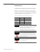
Relay Indicator
Basic Operations
Powering Up the Module
The module performs a self-test at power-up. The self-test includes an LED
test and a device test. During the LED test, the indicators will be turned on
independently and in sequence for approximately 0.25 seconds.
The device test occurs after the LED test. The Module Status (MS) indicator is
used to indicate the status of the device self-test.
Refer to Module Indicators on page 37 for more information about the LED
indicators.
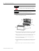
Manually Resetting Relays
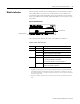
The XM-120 has an external reset switch located on top of the module, as
shown in Figure 2.24.
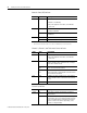
Color State Description
Red Off On-board relay is not activated.
Solid On-board relay is activated.
MS Indicator State Description
Flashing Red and Green Device self-test is in progress.
Solid Green or Flashing Green Device self-test completed successfully,
and the firmware is valid and running.
Flashing Red Device self-test completed, the hardware is
OK, but the firmware is invalid. Or, the
firmware download is in progress.
Solid Red Unrecoverable fault, hardware failure, or
Boot Loader program may be corrupted.