
Owner's manual

Publication GMSI10-UM010C-EN-P - May 2010
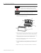
38 Installing the XM-120 Eccentricity Module
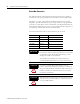
Network Status (NS) Indicator
1 Normal condition when the module is not a slave to an XM-440, PLC, or other master device.
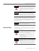
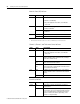
Channel 1, Channel 2, and Tachometer Status Indicators
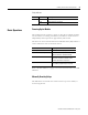
Eccentricity Indicator
Color State Description
No color Off Module is not online.
• Module is autobauding.
• No power applied to the module, look at Module
Status LED.
Green Flashing Module is online (DeviceNet) but no connections are
currently established.
1
Solid Module is online with connections currently
established.
Red Flashing One or more I/O connections are in the timed-out state.
Solid Failed communications (duplicate MAC ID or Bus-off).
Color State Description
No color Off • Normal operation within alarm limits on the channel.
• No power applied to the module, look at Module
Status LED.
Yellow Solid An alert level alarm condition exists on the channel
(and no transducer fault, tachometer fault, or danger
level alarm condition exists).
Flashing Tach
LED
A tachometer fault (no transducer fault) condition
exists on the tachometer channel
Flashing CH1/2
LED
A tachometer fault condition exists and the channel’s
alarm speed range is enabled (and no transducer fault
on the channel’s transducer).
Red Solid A danger level alarm condition exists on the channel
(and no transducer fault or tachometer fault condition
exists).
Flashing A transducer fault condition exists on the channel.
Color State Description
Yellow Off Either alarm is actively monitoring the eccentricity
measurement.
Solid Neither alarm is actively monitoring the eccentricity
measurement. This occurs when both alarms have the
status of DISARM (alarms are disabled, the machine
speed is outside of the alarm’s speed range, or the
module is in Program mode).