XM-120 Eccentricity Module User Guide Firmware Revision 5 1440-VST02-01RA
Important User Information Solid state equipment has operational characteristics differing from those of electromechanical equipment. Safety Guidelines for the Application, Installation and Maintenance of Solid State Controls (publication SGI-1.1 available from your local Rockwell Automation sales office or online at http://literature.rockwellautomation.com) describes some important differences between solid state equipment and hardwired electromechanical devices.
Safety Approvals The following information applies when operating this equipment in hazardous locations. Informations sur l’utilisation de cet équipement en environnements dangereux. Products marked "CL I, DIV 2, GP A, B, C, D" are suitable for use in Class I Division 2 Groups A, B, C, D, Hazardous Locations and nonhazardous locations only. Each product is supplied with markings on the rating nameplate indicating the hazardous location temperature code.
Table of Contents Chapter 1 Introduction Introducing the Eccentricity Module . . . . . . . . . . . . . . . . . . . . . . . . . . . 1 Eccentricity Module Components. . . . . . . . . . . . . . . . . . . . . . . . . . . . . . 2 Using this Manual. . . . . . . . . . . . . . . . . . . . . . . . . . . . . . . . . . . . . . . . . . . 3 Organization. . . . . . . . . . . . . . . . . . . . . . . . . . . . . . . . . . . . . . . . . . . . 3 Document Conventions . . . . . . . . . . . . . . . . . . . . . . . . . . . . .
Table of Contents vi I/O Data Parameters . . . . . . . . . . . . . . . . . . . . . . . . . . . . . . . . . . . . . . . 56 Data Parameters . . . . . . . . . . . . . . . . . . . . . . . . . . . . . . . . . . . . . . . . . . . 57 Monitor Data Parameters . . . . . . . . . . . . . . . . . . . . . . . . . . . . . . . . 58 Alarm and Relay Status Parameters . . . . . . . . . . . . . . . . . . . . . . . . 59 Device Mode Parameters . . . . . . . . . . . . . . . . . . . . . . . . . . . . . . . . . . . .
Table of Contents vii Analog Input Point Object (Class ID 0AH) . . . . . . . . . . . . . . . . . . . . . 88 Class Attributes . . . . . . . . . . . . . . . . . . . . . . . . . . . . . . . . . . . . . . . . 88 Instances. . . . . . . . . . . . . . . . . . . . . . . . . . . . . . . . . . . . . . . . . . . . . . 88 Instance Attributes. . . . . . . . . . . . . . . . . . . . . . . . . . . . . . . . . . . . . . 89 Services . . . . . . . . . . . . . . . . . . . . . . . . . . . . . . . . . . . . . . . . . . . . . .
Table of Contents viii 4-20 mA Output Object (Class ID 32AH) . . . . . . . . . . . . . . . . . . . . . 106 Class Attributes . . . . . . . . . . . . . . . . . . . . . . . . . . . . . . . . . . . . . . . 106 Instances. . . . . . . . . . . . . . . . . . . . . . . . . . . . . . . . . . . . . . . . . . . . . 106 Instance Attributes. . . . . . . . . . . . . . . . . . . . . . . . . . . . . . . . . . . . . 107 Services . . . . . . . . . . . . . . . . . . . . . . . . . . . . . . . . . . . . . . . . . . . . . .
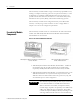
Chapter 1 Introduction This chapter provides an overview of the XM-120 Eccentricity module. It also discusses the components of the module. For information about Introducing the Eccentricity Module 1 Eccentricity Module Components 2 Using this Manual 3 IMPORTANT Introducing the Eccentricity Module See page This manual only describes how to install and use the XM-120 Eccentricity module.
2 Introduction The Eccentricity module includes a single on-board relay, expandable to five, making it a complete monitoring system. It can operate stand-alone, or it can be deployed on a standard or dedicated DeviceNet network where it can provide real-time data and status information to other XM modules, PLCs, distributed control systems (DCS), and Condition Monitoring Systems.
Introduction Using this Manual 3 This manual introduces you to the XM-120 Eccentricity module. It is intended for anyone who installs, configures, or uses the XM-120 Eccentricity module. Organization To help you navigate through this manual, it is organized in chapters based on these tasks and topics. Chapter 1 "Introduction" contains an overview of this manual and the XM-120 Eccentricity module.
4 Introduction The XM-120 Eccentricity module is referred to as XM-120, Eccentricity module, device, or module throughout this manual. TIP EXAMPLE Publication GMSI10-UM010C-EN-P - May 2010 A tip indicates additional information which may be helpful. This convention presents an example.
Chapter 2 Installing the XM-120 Eccentricity Module This chapter discusses how to install and wire the XM-120 Eccentricity module. It also describes the module indicators and the basic operations of the modules.
6 Installing the XM-120 Eccentricity Module XM Installation Requirements This section describes wire, power, and grounding requirements for an XM system. Wiring Requirements Use solid or stranded wire. All wiring should meet the following specifications: • 14 to 22 AWG copper conductors without pretreatment; 8 AWG required for grounding the DIN rail for electromagnetic interference (emi) purposes • Recommended strip length 8 millimeters (0.
Installing the XM-120 Eccentricity Module 7 Figure 2.
8 Installing the XM-120 Eccentricity Module IMPORTANT See Application Technique "XM Power Supply Solutions", publication ICM-AP005A-EN-E, for guidance in architecting power supplies for XM systems. Grounding Requirements Use these grounding requirements to ensure safe electrical operating circumstances, and to help avoid potential emi and ground noise that can cause unfavorable operating conditions for your XM system.
Installing the XM-120 Eccentricity Module 9 Figure 2.
10 Installing the XM-120 Eccentricity Module Figure 2.3 DIN Rail Grounding Block Panel/Wall Mount Grounding The XM modules can also be mounted to a conductive mounting plate that is grounded. See Figure 2.5. Use the grounding screw hole provided on the terminal base to connect the mounting plate the Chassis terminals. Figure 2.
Installing the XM-120 Eccentricity Module 11 Figure 2.5 Panel/Wall Mount Grounding 1 Power Supply 1 Power Supply 1 Use 14 AWG wire.
12 Installing the XM-120 Eccentricity Module 24V Common Grounding 24 V power to the XM modules must be grounded. When two or more power supplies power the XM system, ground the 24 V Commons at a single point, such as the ground bus bar. IMPORTANT IMPORTANT If it is not possible or practical to ground the -24Vdc supply, then it is possible for the system to be installed and operate ungrounded.
Installing the XM-120 Eccentricity Module 13 Figure 2.6 Grounded DeviceNet V- at XM Module To Ground Bus ATTENTION Use of a separate DeviceNet power supply is not permitted. See Application Technique "XM Power Supply Solutions", publication ICM-AP005A-EN-E, for guidance in using XM with other DeviceNet products. For more information on the DeviceNet installation, refer to the ODVA Planning and Installation Manual - DeviceNet Cable System, which is available on the ODVA web site (http://www.odva.org).
14 Installing the XM-120 Eccentricity Module The terminal base can be DIN rail or wall/panel mounted. Refer to the specific method of mounting below. ATTENTION The XM modules make a chassis ground connection through the DIN rail. Use zinc plated, yellow chromated steel DIN rail to assure proper grounding. Using other DIN rail materials (e.g. aluminum, plastic, etc.), which can corrode, oxidize or are poor conductors can result in improper or intermittent platform grounding.
Installing the XM-120 Eccentricity Module 15 3. Rotate the terminal base onto the DIN rail with the top of the rail hooked under the lip on the rear of the terminal base. 4. Press down on the terminal base unit to lock the terminal base on the DIN rail. If the terminal base does not lock into place, use a screwdriver or similar device to open the locking tab, press down on the terminal base until flush with the DIN rail and release the locking tab to lock the base in place.
16 Installing the XM-120 Eccentricity Module 5. Gently push the side connector into the side of the neighboring terminal base to complete the backplane connection. Panel/Wall Mounting Installation on a wall or panel consists of: • laying out the drilling points on the wall or panel • drilling the pilot holes for the mounting screws • installing the terminal base units and securing them to the wall or panel Use the following steps to install the terminal base on a wall or panel.
Installing the XM-120 Eccentricity Module 17 1. Lay out the required points on the wall/panel as shown in the drilling dimension drawing below. Side Connector 2. Drill the necessary holes for the #6 self-tapping mounting screws. 3. Secure the terminal base unit using two #6 self-tapping screws. 4. To install another terminal base unit, retract the side connector into the base unit. Make sure it is fully retracted. 5. Position the terminal base unit up tight against the neighboring terminal base.
18 Installing the XM-120 Eccentricity Module Figure 2.7 XM-940 Terminal Base Unit XM-940 (Cat. No. 1440-TB-A) Terminal Block Assignments The terminal block assignments and descriptions for the Eccentricity module are shown below. ATTENTION The terminal block assignments are different for different XM modules. The following table applies only to the XM-120 Eccentricity module revision D01 (and later). If you have an earlier revision of the module, refer to Appendix D for its terminal block assignments.
Installing the XM-120 Eccentricity Module WARNING 19 EXPLOSION HAZARD Do not disconnect equipment unless power has been removed or the area is known to be nonhazardous. Do not disconnect connections to this equipment unless power has been removed or the area is known to be nonhazardous. Secure any external connections that mate to this equipment by using screws, sliding latches, threaded connectors, or other means provided with this product. Terminal Block Assignments No.
20 Installing the XM-120 Eccentricity Module Terminal Block Assignments No.
Installing the XM-120 Eccentricity Module 21 Connecting the Power Supply Power supplied to the module must be nominally 24 Vdc (±10%) and must be a Class 2 rated circuit. Wire the DC-input power supply to the terminal base unit as shown in Figure 2.8. Figure 2.
22 Installing the XM-120 Eccentricity Module Connecting the Relays The XM-120 has both Normally Open (NO) and Normally Closed (NC) relay contacts. Normally Open relay contacts close when the control output is energized. Normally Closed relay contacts open when the control output is energized. The alarms associated with the relay and whether the relay is normally de-energized (non-failsafe) or normally energized (failsafe) depends on the configuration of the module.
Installing the XM-120 Eccentricity Module 23 Table 2.1 Relay Connections for XM-120 Configured for Failsafe Operation Relay 1 Terminals Nonalarm Alarm Wire Contacts Contact 1 Contact 2 Closed Opened COM 47 50 NO 48 49 COM 47 50 NC 46 51 Opened Closed Configured for Non-failsafe Operation Relay 1 Terminals Nonalarm Alarm Wire Contacts Contact 1 Contact 2 Closed Opened COM 47 50 NC 46 51 COM 47 50 NO 48 49 Opened Closed Figures 2.9 and 2.
24 Installing the XM-120 Eccentricity Module Figure 2.10 Relay Connection - Failsafe, Alarm Condition Non-failsafe, Nonalarm Condition Alternate Relay Wiring Figures 2.11 and 2.12 show how to wire both ends of a single external indicator to the XM terminal base for failsafe, nonalarm or alarm condition or non-failsafe, nonalarm or alarm condition. Figure 2.
Installing the XM-120 Eccentricity Module 25 Figure 2.12 Relay Connection - Failsafe, Alarm Condition Non-failsafe, Nonalarm Condition Connecting the Tachometer Signal The XM-120 provides a single tachometer input signal. The signal processing performed on the tachometer signal depends on the configuration of the module. See page 47 for a description of the tachometer parameters. IMPORTANT If you are not using the tachometer input, set the Pulses Per Revolution parameter to zero (0).
26 Installing the XM-120 Eccentricity Module Connecting a Magnetic Pickup Tachometer Figure 2.13 shows the wiring of a magnetic pickup tachometer to the terminal base unit. Figure 2.13 Magnetic Pickup Tachometer Signal Connection Connecting a Hall Effect Tachometer Sensor Figure 2.14 shows the wiring of a Hall Effect Tachometer Sensor, Cat. No. EK-44395, to the terminal base unit. Figure 2.
Installing the XM-120 Eccentricity Module 27 Connecting a Non-Contact Sensor to the Tachometer Signal Figure 2.15 shows the wiring of a non-contact sensor to the tachometer input signal. Figure 2.15 Non-Contact Sensor to Tachometer Signal Connection 4 18 Signal Common 20 21 31 Tach Input Signal -24V DC -24 SIG COM S hi e ld F lo a t i n g S h i el d Isolated Sensor Driver Connecting the Buffered Outputs The XM-120 provides buffered outputs of all transducer input signals.
28 Installing the XM-120 Eccentricity Module Figure 2.16 Buffered Output Connections IMPORTANT Applies only to XM-120 module revision D01 (and later). The voltage operating range of the buffered outputs must be configured to coincide with the corresponding transducer bias range. This operating range is configured by placing a jumper from terminal 5 (channel 1) and terminal 22 (channel 2) to either terminal 6 (Positive Buffer Bias) or terminal 21 (Buffer -), depending on the transducer. See Table 2.2.
Installing the XM-120 Eccentricity Module 29 Connecting a Non-Contact Sensor The Eccentricity module accepts input from any Allen-Bradley non-contact eddy current probe. The figures below show the wiring of a non-contact eddy probe to the terminal base unit. IMPORTANT ATTENTION IMPORTANT Figures 2.17 and 2.18 show the wiring to the XM-120 module revision D01 (and later). If you have an earlier revision of the module, refer to Appendix D for wiring information.
30 Installing the XM-120 Eccentricity Module Figure 2.18 Non-contact Sensor to Channel 2 Wiring TYPICAL WIRING FOR NON-CONTACT SENSOR TO XM-120 ECCENTRICITY MODULE CHANNEL 2 Isolated Sensor Driver -24 SIG COM Shield Floating Signal Common Channel 2 Input Signal Shield -24V DC 17 38 21 22 1 Jumpering terminal 21 to terminal 22 configures CH 2 buffer for -24V to +9V (See Table 2.
Installing the XM-120 Eccentricity Module 31 Figure 2.19 Remote Relay Reset Signal Connection ATTENTION The Switch Input circuits are functionally isolated from other circuits. It is recommended that the Switch RTN signal be grounded at a signal point. Connect the Switch RTN signal to the XM terminal base (Chassis terminal) or directly to the DIN rail, or ground the signal at the switch or other equipment that is wired to the switch.
32 Installing the XM-120 Eccentricity Module Connecting the 4-20 mA Outputs The module includes an isolated 4-20 mA per channel output into a maximum load of 300 ohms. The measurements that the 4-20 mA output tracks and the signal levels that correspond to the 4 mA and 20 mA are configurable. Refer to 4-20 mA Output Parameters on page 55 for details. Wire the 4-20 mA outputs to the terminal base unit as shown in Figure 2.21. Figure 2.
Installing the XM-120 Eccentricity Module 33 The DB-9 connector should be wired to the terminal block as shown. XM-120 Terminal Base Unit (Cat. No. 1440-TB-A) DB-9 Female Connector TX Terminal (terminal 7) ---------------------- Pin 2 (RD - receive data) RX Terminal (terminal 8) ---------------------- Pin 3 (TD - transmit data) RTN Terminal (terminal 9) --------------------- Pin 5 (SG - signal ground) • Mini Connector - The mini connector is located on the top of the module, as shown below.
34 Installing the XM-120 Eccentricity Module DeviceNet Connection The XM-120 includes a DeviceNet™ connection that allows the module to communicate with a programmable controller, DCS, or another XM module. DeviceNet is an open, global, industry-standard communications network designed to provide an interface through a single cable from a programmable controller to a smart device such as the XM-120.
Installing the XM-120 Eccentricity Module ATTENTION IMPORTANT 35 The DNet V+ and DNet V- terminals are inputs to the XM module. Do not attempt to pass DeviceNet power through the XM terminal base to other non-XM equipment by connecting to these terminals. Failure to comply may result in damage to the XM terminal base and/or other equipment.
36 Installing the XM-120 Eccentricity Module WARNING IMPORTANT When you insert or remove the module while power is on, an electrical arc can occur. This could cause an explosion in hazardous location installations. Be sure that power is removed or the area is nonhazardous before proceeding. Install the overlay slide label to protect serial connector and electronics when the serial port is not in use. 1.
Installing the XM-120 Eccentricity Module Module Indicators 37 The Eccentricity module has seven LED indicators, which include a module status (MS) indicator, a network status (NS) indicator, a status indicator for each channel (CH1, CH2, and TACH), an activation indicator for Eccentricity, and a status indicator for the Relay. The LED indicators are located on top of the module. Figure 2.
38 Installing the XM-120 Eccentricity Module Network Status (NS) Indicator Color State Description No color Off Module is not online. • Module is autobauding. • No power applied to the module, look at Module Status LED. Green Red 1 Flashing Module is online (DeviceNet) but no connections are currently established.1 Solid Module is online with connections currently established. Flashing One or more I/O connections are in the timed-out state.
Installing the XM-120 Eccentricity Module 39 Relay Indicator Basic Operations Color State Description Red Off On-board relay is not activated. Solid On-board relay is activated. Powering Up the Module The module performs a self-test at power-up. The self-test includes an LED test and a device test. During the LED test, the indicators will be turned on independently and in sequence for approximately 0.25 seconds. The device test occurs after the LED test.
40 Installing the XM-120 Eccentricity Module Figure 2.24 Reset Switch Press the Reset Switch to reset the relays The switch can be used to reset all latched relays in the module. This includes the relays in the Expansion Relay Module when it is attached to the XM-120. IMPORTANT Installing the XM-120 Eccentricity Firmware The Reset switch resets the relays only if the input is no longer in alarm or the condition that caused the alarm is no longer present.
Installing the XM-120 Eccentricity Module 41 4. Power up the XM-120 module if you haven’t already done so, and start the XM Serial Configuration Utility program. Click the Start program, and then select Programs > Entek > XM > Serial Config Utility. 5. Click the Configure button on the XM Serial Configuration Utility screen. The XM-120 Dynamic Measurement Module Configuration Tool screen appears. 6. Click the Module tab. Click this button to update the device with the Eccentricity firmware 7.
42 Installing the XM-120 Eccentricity Module 9. Click Open to start the firmware update and click Yes to confirm. The Configuration Tool begins the update and shows its progress in the Progress dialog box. 10. When the update completes, the message "The module is configured with the factory defaults. You need to download a configuration." appears. Click OK. 11. Click OK again to return to the XM Serial Configuration Utility screen. Notice that the XM Module icon displays XM-12E instead of XM-120. 12.
Chapter 3 Configuration Parameters This chapter provides a complete listing and description of the Eccentricity parameters. The parameters can be viewed and edited using the XM Serial Configuration Utility software and a personal computer. If the module is installed on a DeviceNet network, configuring can also be performed using a network configuration tool such as RSNetWorx (Version 3.0 or later). Refer to your configuration tool documentation for instructions on configuring a device.
44 Configuration Parameters Channel Transducer Parameters The channel transducer parameters define the characteristics of the transducers you will be using with the module. Use the parameters to configure the transducer sensitivity, and operating range. There are two instances of the channel transducer parameters, one for each channel. TIP The Channel LED will flash red when a transducer fault condition exists on the channel even if you are not using the channel.
Configuration Parameters Measurement Parameters 45 Eccentricity Measurement Parameters Use these parameters to configure the engineering units and update rate for the eccentricity measurements. There are two instances of the eccentricity measurement parameters, one for each channel. TIP The Eccentricity Update Rate parameter is for installations where the tachometer signal is not available.
46 Configuration Parameters The Waveform Period and the Number of Points must be configured such that the sampling rate (Number of Points/Waveform Period) is from 0.32 Hz to 187.5 Hz. The module will automatically use 187.5 Hz when the sampling rate is above 93.75, resulting in waveforms collected with a different period than specified. TIP The table below shows examples.
Configuration Parameters 47 Speed Measurement Parameter Use the speed measurement parameter to configure the filtering performed on the speed measurement. Speed Measurement Parameter Parameter Name Description Values/Comments Exponential Averaging Time Constant Sets the 3-dB bandwidth for the digital filter used to calculate the Speed Value. The 3-dB bandwidth is roughly equal to 1 / (2π x Exponential Averaging Time Constant).
48 Configuration Parameters Tachometer Signal Processing Parameters IMPORTANT If you are not using the tachometer channel, set the Pulses per Revolution to zero. This will disable the tachometer measurement, and prevent the module from indicating a tachometer fault. Tachometer Signal Processing Parameters Parameter Name Description Values/Comments Pulses Per Revolution The number of tachometer signal pulses per revolution of the shaft (number of gear teeth).
Configuration Parameters 49 Tachometer Signal Processing Parameters Parameter Name Description Values/Comments Trigger Slope The input signal slope to be used as the trigger value when in Manual Trigger mode. Options: Positive Negative Note: This value is not used in Auto Trigger mode. Alarm Parameters The Alarm parameters control the operation of the alarms (alert and danger level) and provide alarm status. The Eccentricity module provides two alarms, one per eccentricity channel.
50 Configuration Parameters Alarm Parameters Parameter Name Description Values/Comments Condition Controls when the alarm should trigger. Options: Greater Than Less Than Inside Range Outside Range • Greater than - Triggers the alarm when the measurement value is greater than or equal to the Alert and Danger Threshold values. The Danger Threshold value must be greater than or equal to the Alert Threshold value for the trigger to occur.
Configuration Parameters 51 Alarm Parameters Parameter Name Description Values/Comments Alert Threshold (High) The threshold value for the alert (alarm) condition. Same measurement unit as the Eccentricity Unit selection for the specified channel. Note: This parameter is the greater threshold value when Condition is set to "Inside Range" or "Outside Range." Danger Threshold (High) The threshold value for the danger (shutdown) condition.
52 Configuration Parameters Alarm Parameters Parameter Name Description Values/Comments Speed Range Low The lesser threshold of the machine speed range. This value must be less than the Speed Range High value. RPM This parameter is not used when Speed Range Enabled is disabled. Speed Range High The greater threshold of the machine speed range. This value must be greater than the Speed Range Low value. This parameter is not used when Speed Range Enabled is disabled.
Configuration Parameters 53 Relay Parameters Parameter Name Description Options/Comments Name (XM Serial Configuration Utility only) A descriptive name to help identify the relay in the XM Serial Configuration Utility. Maximum 18 characters Enable Enable/disable the selected relay. Note: The Relay Current Status is set to "Not Activated" when the relay is disabled. See page 57.
54 Configuration Parameters Relay Parameters Parameter Name XM Configuration EDS File Utility Alarm Status to Activate On Description Options/Comments Sets the alarm conditions that will cause the relay to activate. You can select more than one. Options: Normal Danger Xdcr Fault Tacho Fault Alert Disarm Module Fault Alarm Levels • Normal - The current measurement is not within excess of any alarm thresholds.
Configuration Parameters 55 Relay Parameters Parameter Name Description XM Configuration EDS File Utility Failsafe Relay Failsafe Option Determines whether the relay is failsafe or non-failsafe. Failsafe operation means that when in alarm, the relay contacts are in their "normal," de-energized, or "shelf-state" positions. In other words, normally closed relays are closed in alarm, and normally open relays are open in alarm. With failsafe operation, a power failure equals an alarm.
56 Configuration Parameters IMPORTANT IMPORTANT Measured values between Min Range and Max Range are scaled into the range from 4.0 to 20.0 to produce the output value. The Min Range value does not have to be less than the Max Range value. If the Min Range value is greater than the Max Range value, then the output signal is effectively inverted from the input signal. The 4-20 mA outputs are either on or off.
Configuration Parameters 57 I/O Data Parameters Parameter Name Description Values/Comments COS Output (XM Serial Configuration Utility only) The Assembly instance used for the COS message. The COS message is used to produce the Alarm and Relay status for the module. The COS Output cannot be changed. Refer to COS Message Format on page 73 for more information. Poll Size Sets the size (number of bytes) of the Poll response The minimum size is 4 bytes and the message.
58 Configuration Parameters Monitor Data Parameters Monitor Data Parameters Parameter Name Description Values/Comments Channel Status (XM Serial Configuration Utility only) States whether a fault condition exists on the associated channel. If a fault exists, the eccentricity measurement may not be accurate.
Configuration Parameters 59 Alarm and Relay Status Parameters Alarm and Relay Status Parameters Parameter Name XM Configuration EDS File Utility Alarm Relay Status Description Values/Comments States the current status of the alarm. Possible status values: • Normal - The alarm is enabled, the device is in Run mode, there is no transducer fault, and the current measurement is not within the Alert or Danger Threshold value(s).
60 Configuration Parameters Device Mode Parameters The Device Mode parameters are used to control the functions and the behavior of the device. IMPORTANT The XM Serial Configuration Utility handles these parameters automatically and transparently to the user. Device Mode Parameters Parameter Name Description Values/Comments Device Mode Sets the current operation mode of the device. Refer to Changing Operation Modes on page 67 for more information.
Appendix A Specifications The Appendix lists the technical specifications for the Eccentricity module. XM-120 Eccentricity Technical Specifications Product Feature Specification Communications DeviceNet Standard DeviceNet protocol for all functions NOTE: The XM-120 uses only the DeviceNet protocol, not power. Module power is provided independently.
62 Specifications XM-120 Eccentricity Technical Specifications Product Feature Specification Inputs 2 Channels Eddy current transducer signals Transducer Power Constant voltage (+24V dc)* None (voltage input) *Tachometer may be powered, constant voltage, or configured as voltage input. Voltage Range Selectable in software as 0 to ±20 V (min) 40 V max. peak-to-peak Sensitivity User configurable in software Input Impedance Greater than 100kohms Tachometer 1 Tachometer Input ±25 V (50 V max.
Specifications 63 XM-120 Eccentricity Technical Specifications Product Feature Specification Signal Conditioning Frequency Response Peak-to-peak Eccentricity, Max Gap, Min Gap: 0.0039 to 20 Hz (0.235 to 1200 cpm) Gap: 0 to 20 Hz (0 to 1200 cpm) Accuracy ±1% of measurement Noise Floor: 8 mV RMS Specified at ambient temperature of +25°C (+77°F) Gap Resolution 5.
64 Specifications XM-120 Eccentricity Technical Specifications Product Feature Specification Relays Number Single on-board relay, two sets of contacts DPDT (2 Form C) Four additional relays when interconnected to an XM-441 Expansion Relay module, or Four virtual relays whose status can be used by remote Control Systems or the XM-440 Master Relay module On-board Relay Rating Maximum Voltage: 120V dc, 125V ac Maximum Current: 3.5 A* Minimum Current: 0 Maximum Power: 60 W, 62.
Specifications 65 XM-120 Eccentricity Technical Specifications Product Feature Specification Non-Volatile Configuration A copy of the module configuration is retained in non-volatile memory from where it is loaded upon power up*. *The configuration stored in non-volatile memory can be deleted only by a module-reset command sent via the serial interface, using the Serial Configuration Utility, or via DeviceNet from any compliant software application.
66 Specifications XM-120 Eccentricity Technical Specifications Product Feature Approvals (when product or packaging is marked) Specification UL UL Listed for Ordinary Locations UL UL Listed for Class I, Division 2 Group A, B, C, and D Hazardous Locations CSA CSA Certified Process Control Equipment CSA CSA Certified Process Control Equipment for Class I, Division 2 Group A, B, C, and D Hazardous Locations EEX* European Union 94/9/EEC ATEX Directive, compliant with EN 50021; Potentially Explosive
Appendix B DeviceNet Information Electronic Data Sheets Electronic Data Sheet (EDS) files are simple text files used by network configuration tools such as RSNetWorx (Version 3.0 or later) to help you identify products and easily commission them on a network. The EDS files describe a product’s device type, product revision, and configurable parameters on a DeviceNet network. The EDS files for the XM modules are installed on your computer with the XM configuration software.
68 DeviceNet Information Transition to Program Mode Parameter values can only be downloaded to an XM module while the module is in Program mode. Any attempt to download a parameter value while the module is in Run mode will result in a Device State Conflict error. To transition an XM module from Run mode to Program mode on a DeviceNet network, set the Device Mode parameter to "Program mode" and click Apply.
DeviceNet Information 69 The table below defines services supported by the XM modules. The table includes the service codes, classes, instances, and attributes by their appropriate hexadecimal codes. Use the Class Instance Editor in RSNetWorx to execute these services, as illustrated in the example below.
70 DeviceNet Information Example To save the configuration parameters to the non-volatile memory (EEPROM), fill in the Class Instance Editor as shown below. Clear Send the attribute ID and then enter the Class (320 hex) and Instance (1) Select the Save service code Click Execute to initiate the action Invalid Configuration Errors A Start or Save service request to an XM module may return an Invalid Device Configuration error when there is a conflict amongst the configuration settings.
DeviceNet Information 71 Additional Error Codes returned with the Invalid Device Configuration Error (0xD0) Eccentricity I/O Message Formats Error Code (Hex) Description 0A Too many alarms associated with a single measurement. 0B Invalid node address in the alarm list. 0C Too many alarms in the alarm list. Or, no alarms in the alarm list. 0D Alarm levels cannot be zero for alarms that are enabled. 0E Too many slaves in the scanner’s input data table.
72 DeviceNet Information The Poll response data can also be requested explicitly through Assembly Object (Class ID 0x4), Instance 101 (0x65), Data Attribute (3). The following tables show the static data format of Assembly instances 101– 104.
DeviceNet Information 73 Eccentricity Assembly Instance 103 Data Format Byte Definition 24–27 Channel 2 Gap value 28–31 Channel 1 Maximum Gap value 32–35 Channel 2 Maximum Gap value Eccentricity Assembly Instance 104 Data Format Byte Definition 0–3 Channel 1 Eccentricity value 4–7 Channel 1 Gap value 8–11 Channel 1 Minimum Gap value 12–15 Channel 1 Maximum Gap value 16–19 Speed 20–23 Channel 2 Eccentricity value 24–27 Channel 2 Gap value 28–31 Channel 2 Minimum Gap value 32–35 C
74 DeviceNet Information XM Status Values The following tables describe the XM Status values that are included in the COS messages.
DeviceNet Information 75 • The ADR scanner can not download the configuration data to an XM module if the module has a saved configuration in its non-volatile memory. This happens because the saved configuration is restored and the module enters Run mode when the power is cycled. (Configuration parameters cannot be downloaded while an XM module is in Run mode.) XM modules must be in Program mode for the ADR configuration to be downloaded and this occurs only when there is no saved configuration.
76 DeviceNet Information – All SU/CD Trend related parameters – Custom Assembly structure (see page 56) • The ADR and trigger group functions cannot be used together. A module can have only one primary master so a module cannot be both configured for ADR and included in a trigger group. The ADR scanner must be the primary master for the modules configured for ADR. The XM-440 Master Relay module must be the primary master for modules included in a trigger group.
Appendix C DeviceNet Objects Appendix C provides information on the DeviceNet objects supported by the Eccentricity module.
78 DeviceNet Objects The Identity Object provides identification and general information about the device. Identity Object (Class ID 01H) Class Attributes The Identity Object provides no class attributes. Instance Attributes Table C.
DeviceNet Objects 79 Table C.2 Identity Object Status Bit Name Description 4 Boot Program Vendor-specific, indicates that the boot program is running. The Main Application must be corrupt or missing. 5-7 Vendor-specific, not implemented 8 Minor Recoverable Fault Set whenever there is a transducer or tachometer fault. 9 Minor Unrecoverable Fault Not implemented 10 Major Recoverable Fault Set when the module detects a major problem that the user may be able to recover from.
80 DeviceNet Objects The DeviceNet Object is used to provide the configuration and status of a physical attachment to DeviceNet. DeviceNet Object (Class ID 03H) Class Attributes Table C.4 DeviceNet Object Class Attributes Attr ID Access Rule Name Data Type Default Value 1 Get Revision UINT 2 Instance Attributes Table C.
DeviceNet Objects 81 rate detection instead. This means that the module will determine the network baud rate by listening for network traffic before attempting to go online. Services Table C.6 DeviceNet Object Services Service Code Class/Instance Usage Name 0Eh Class/Instance Get_Attribute_Single 10h Instance Set_Attribute_Single1 4Bh Instance Allocate_Master/Slave_Connetion_Set 4Ch Instance Release_Group_2_Identifier_Set 1 Attributes can only be set while the device is in Program Mode.
82 DeviceNet Objects Table C.8 Assembly Object Instances Instance Name Type Description 101 Default Poll Response Message Input Measurement values 102 - 106 Alternate Poll Response Message Input Measurement values 199 Alternate Dynamic Poll Response Message Input User configurable measurement values and configuration parameters Instance Attributes Table C.
DeviceNet Objects 83 Table C.10 Instance 100 Data Format (Alarm and Relay Status Values Assembly) Byte Bit 7 Bit 6 Bit 5 Bit 4 Bit 3 Bit 2 Bit 1 Bit 0 2 Relay 3 Status 0 0 0 3 Relay 4 Status 0 0 0 4 Relay 5 Status 0 0 0 Instance 101 - Eccentricity Module Measurements This is the default assembly that is sent within the I/O Poll Response message when an I/O Poll Request is received from a DeviceNet master. Table C.
84 DeviceNet Objects Instance 103 - Eccentricity Module Measurements This is an alternate assembly for the I/O Poll Response message. Table C.
DeviceNet Objects 85 The dynamic Assembly can include all of the measurement values included in Assembly instance 101. In addition, the dynamic Assembly can include the following configuration parameters. Table C.
86 DeviceNet Objects Services Table C.16 Assembly Object Services Service Code Class/Instance Usage Name 0Eh Class/Instance Get_Attribute_Single 10h Instance Set_Attribute_Single 08h Class Create 09h Instance Delete The Connection Object allocates and manages the internal resources associated with both I/O and Explicit Messaging Connections. Connection Object (Class ID 05H) Class Attributes The Connection Object provides no class attributes. Instances Table C.
DeviceNet Objects 87 Table C.18 Connection Object Instance Attributes Attr ID Access Rule Name Data Type Description 4 Get Produced Connection ID UINT Placed in CAN Identifier Field when the Connection transmits. 5 Get Consumed Connection ID UINT CAN Identifier Field value that denotes message to be received. 6 Get Initial Comm Characteristics BYTE Defines the Message Group(s) across which productions and consumptions associated with this Connection occur.
88 DeviceNet Objects Services Table C.19 Connection Object Services Analog Input Point Object (Class ID 0AH) Service Code Class/Instance Usage Name 05h Instance Reset 0Eh Instance Get_Attribute_Single 10h Instance Set_Attribute_Single The Analog Input Point Object is used to model the Eccentricity measurements made by the Eccentricity module. Class Attributes Table C.
DeviceNet Objects 89 Instance Attributes Table C.22 Analog Input Point Object Class Attributes Attr ID Access Rule Name Data Type Description Semantics 3 Get Value REAL Measurement value The measured vale in units specified by the Data Units attribute. 4 Get Status BOOL Indicates if a fault or alarm has occurred. 0 = Operating without alarms or faults 1 = Alarm or fault condition exists. The Value attribute may not represent the actual field value.
90 DeviceNet Objects The Parameter Object provides the interface to the Eccentricity configuration data. There are 18 Parameter Object instances implemented in the Eccentricity module. Parameter Object (Class ID 0FH) Instances 1-4 and 7-16 are implemented to provide an alternate method of setting the configuration parameters with ENGUNIT or EPATH data type.
DeviceNet Objects 91 Table C.
92 DeviceNet Objects Instance Attributes Table C.26 Parameter Object Instance Attributes Attr ID Access Rule 1 Set Parameter Value 2 Get Link Path Size USINT Size of Link Path 3 Get Link Path ARRAY of DeviceNet path DeviceNet path to the object for the Parameter value. Segment Type/ Port BYTE See DeviceNet Specification Volume 1 Appendix I for format. Name Data Type Description Semantics Actual value of parameter See Table C.25 for a list of valid values for each instance.
DeviceNet Objects 93 The Acknowledge Handler Object is used to manage the reception of message acknowledgments. This object communicates with a message producing Application Object within a device. The Acknowledge Handler Object notifies the producing application of acknowledge reception, acknowledge timeouts, and production retry limit errors. Acknowledge Handler Object (Class ID 2BH) Class Attributes The Acknowledge Handler Object provides no class attributes.
94 DeviceNet Objects The Alarm Object models a two-stage (alert and danger levels) alarm. Alarm Object (Class ID 31DH) Class Attributes The Alarm Object provides no class attributes. Instances There are 2 instances of this object. Instance Attributes Table C.30 Alarm Object Instance Attributes Attr ID Access Rule Name Data Type Description Semantics 3 Get Alarm Status 3 BITS The current status of the alarm.
DeviceNet Objects 95 Table C.30 Alarm Object Instance Attributes Attr ID Access Rule 11 Get/Set Danger Threshold REAL Low (Counterclockwise) The lesser threshold value for the danger (shutdown) condition for the range condition types. 12 Get/Set Hysteresis REAL The amount on the safe side of a threshold by which the value must recover to clear the alarm. 15 Get/Set Speed Range Enable BOOL Indicates whether this alarm is enabled only within a certain machine speed range.
96 DeviceNet Objects The Device Mode Object is used to control access to the configuration parameters in the module. This object’s Device Mode attribute must be in PROGRAM mode to allow the module’s configuration parameters to be "Set" (see Services). Attempts to set the configuration parameters while the Device Mode is in RUN mode will return an error. Note that the module collects measurements while in RUN mode but not while it is in PROGRAM mode.
DeviceNet Objects 97 Table C.33 Device Mode Object Services Service Code Class/Instance Usage Name Description 06h Instance Start Validate the device configuration settings and transition to the Run state if OK. 05h Instance Reset Transition to the Power Up state. Load the non-volatile configuration and transition to the Run state if saved configuration restored. 16h Instance Save Validate the device configuration settings if necessary and save them to non-volatile memory.
98 DeviceNet Objects Instances There are 5 instances of this object. Instance Attributes Table C.35 Relay Object Instance Attributes Attr ID Access Rule Name Data Type Description Semantics 3 Get Relay Status BOOL The current status of the relay. 0 = Off 1 = On 4 Get/Set Relay Enable BOOL Indicates whether this relay object is enabled. 0 = Disabled 1 = Enabled 5 Get/Set Latch Enable BOOL Indicates whether this relay latches (requires a reset command to deactivate).
DeviceNet Objects 99 Table C.35 Relay Object Instance Attributes Attr ID Access Rule 11 Name Data Type Description Semantics Get/Set Alarm Identifier B EPATH Identifies the second alarm status the relay monitors. See Parameter Object instances 12 to 16. 12 Get/Set Logic USINT Indicates the number of associated alarms that must have a status value specified by Alarm Level in order to activate the relay.
100 DeviceNet Objects Instances There are 2 instances of this object. Instance Attributes Table C.37 Spectrum Waveform Measurement Object Instance Attributes Attr ID Access Rule Name Data Type Description Semantics 3 Get Status BOOL Indicates if a fault or alarm has occurred. 0 = Operating without alarms or faults. 1 = Alarm or fault condition exists. The waveform data may not represent the actual field value. 4 Get Data Units ENGUNIT The units context of the Data attributes.
DeviceNet Objects 101 Get_Waveform_Chunk This service returns a portion of the respective data structure. It is likely that the waveform data structure will be too large to transfer over the network in one message. This service allows the data structures to be transferred over the network in smaller portions so that the explicit message buffer does not need to be so large.
102 DeviceNet Objects The Get_Waveform_Chunk service uses the following request and response parameters. Table C.40 Get_Waveform_Chunk Request Parameters Name Data Type Initial DWORD Offset UINT Number of DWORDs USINT Description of Request Parameters Semantics of Values The offset of the first 32-bit value within the data structure to be returned. 0 <= offset < size of the data structure in DWORDs.
DeviceNet Objects 103 Instance Attributes Table C.42 Speed Measurement Object Instance Attributes Attr ID Access Rule Name Data Type Description Semantics 3 Get Speed Value REAL The measured speed value. CPM 4 Get Status BOOL Indicates if a fault or alarm has occurred. 0 = Operating without alarms or faults 1 = Alarm or fault condition exists. The Speed Value attribute may not represent the actual field value.
104 DeviceNet Objects Instance Attributes Table C.44 Tachometer Channel Object Instance Attributes Attr ID Access Rule 3 Name Data Type Description Semantics Get/Set Number of Pulses per Revolution UINT The number of signal pulses per revolution of the shaft (number of gear teeth). 0 = Tachometer disabled > 0 = Tachometer enabled 4 Get/Set Auto Trigger BOOL Indicates whether the trigger level is determined automatically from the signal.
DeviceNet Objects Transducer Object (Class ID 328H) 105 The Transducer Object models a transducer. Class Attributes The Transducer Object provides no class attributes. Instances There are 3 instances of this object. Transducer Object instance 1 is for Eccentricity Channel 1. Transducer Object instance 2 is for Eccentricity Channel 2. And Transducer Object instance 3 is for the tachometer channel. Instance Attributes Table C.
106 DeviceNet Objects Table C.46 Transducer Object Instance Attributes Attr ID Access Rule Name Data Type Description Semantics 8 Get/Set Fault Low REAL The minimum expected DC Bias voltage from the transducer in volts. Volts 14 Get/Set Name STRING2 A name to help identify this transducer or channel. Services Table C.47 Transducer Object Services Service Code Class/Instance Usage Name Description 0Eh Instance Get_Attribute_Single Returns a single attribute.
DeviceNet Objects 107 Instance Attributes Table C.48 4-20 mA Output Object Instance Attributes Attr ID Access Rule Name Data Type Description Semantics 3 Get Value REAL The current output value. mA 4 Get/Set Enable BOOL Indicates whether this 4-20 mA output is enabled. 0 = Disabled 1 = Enabled 5 Get/Set Max Range REAL The measured value associated with 20 mA. 6 Get/Set Min Range REAL The measured value associated with 4 mA. Services Table C.
108 DeviceNet Objects Publication GMSI10-UM010C-EN-P - May 2010
Appendix D Wiring Connections for Previous Module Revisions Appendix D provides the terminal block assignments and wiring connections of earlier revisions of the XM-120 module (before revision D01). If you have a later revision of the module, refer to Chapter 2 for wiring information. The revision number can be found on the product label which is located on the front of the XM module (see Figure D.1). Figure D.
110 Wiring Connections for Previous Module Revisions WARNING EXPLOSION HAZARD Do not disconnect equipment unless power has been removed or the area is known to be nonhazardous. Do not disconnect connections to this equipment unless power has been removed or the area is known to be nonhazardous. Secure any external connections that mate to this equipment by using screws, sliding latches, threaded connectors, or other means provided with this product. Terminal Block Assignments No.
Wiring Connections for Previous Module Revisions 111 Terminal Block Assignments No.
112 Wiring Connections for Previous Module Revisions Connecting the Transducer The Eccentricity module accepts input from any Allen-Bradley non-contact eddy current probe. Figures D.2 and D.3 show the wiring of a non-contact eddy probe to an earlier revision of the XM-120 module (before revision D01). ATTENTION IMPORTANT You may ground the cable shield at either end of the cable. Do not ground the shield at both ends.
Wiring Connections for Previous Module Revisions 113 Figure D.
114 Wiring Connections for Previous Module Revisions Publication GMSI10-UM010C-EN-P - May 2010
Glossary alarm An alarm alerts you to a change in a measurement. For example, an alarm can notify you when the measured vibration level for a machine exceeds a pre-defined value. Automatic Device Replacement (ADR) A means for replacing a malfunctioning device with a new unit, and having the device configuration data set automatically. The ADR scanner uploads and stores a device’s configuration.
Glossary 116 current configuration The current configuration is the most recently loaded set of configuration parameters in the XM module’s memory. When power is cycled, the current configuration is loaded with either the saved configuration (in EEPROM) or the factory defaults (if there is no saved configuration). In addition, the current configuration contains any configuration changes that have been downloaded to the module since power was applied.
Glossary 117 Help window A window that contains help topics that describe the operation of a program. These topics may include: • • • • An explanation of a command. A description of the controls in a dialog box or property page. Instructions for a task. Definition of a term. MAC ID See node address. master device A device which controls one or more slave devices. The XM-440 Master Relay module is a master device. Node Address A DeviceNet network can have as many as 64 devices connected to it.
Glossary 118 Program mode The XM module is idle. Typically this occurs when the module configuration settings are being updated with the XM Configuration program. In Program mode, the signal processing/measurement process is stopped. The status of the alarms is set to the disarm state to prevent a false alert or danger status. Run mode In Run mode, the module collects measurement data and monitors each measurement device.
Index Numerics 24V common grounding requirements 12 4-20mA Output Object 106 4-20mA output parameters 55 Enable 55 Max Range 55 Min Range 55 4-20mA outputs, wiring 32 A Acknowledge Handler Object 93 Alarm Object 94 alarm parameters 49 Alarm Number 49 Alert Threshold (High) 51 Alert Threshold (Low) 51 Condition 50 Danger Threshold (High) 51 Danger Threshold (Low) 51 Enable 49 Hysteresis 51 Name 49 Speed Range Enable 51 Speed Range High 52 Speed Range Low 52 Analog Input Point Object 88 Assembly Object 81 A
120 Index description configuration parameters 43 XM-120 Eccentricity module 2 XM-121 module 2 XM-441 module 2 XM-940 terminal base 2 Device Mode Object 96 Device Mode parameter 60, 67 Device Mode parameters Autobaud 60 Device Mode 60, 67 DeviceNet connection baud rate 35 node address 35 wiring 34 DeviceNet grounding requirements 12 DeviceNet information automatic device replacement (ADR) 74 EDS files 67 I/O message formats 71 invalid device configuration errors 70 setting the Device Mode parameter 67 XM
Index mounting terminal base unit on DIN rail 13 terminal base unit on panel/walll 16 XM-120 module on terminal base 35 N Network Status (NS) indicator 38 node address 35 normally closed relay contacts 22 normally open relay contacts 22 O operating mode program mode 37, 67 run mode 37, 67 P panel/wall mount grounding requirements 10 Parameter Object 90 poll message format 71 Assembly instance 101 72 Assembly instance 102 72 Assembly instance 103 72 Assembly instance 104 73 power requirements 6 power sup
122 Index W waveform parameters 45 Number of Points 45 Waveform Period 45 wiring to separate power connections 6 to terminal base 17 wiring connections 4-20mA outputs 32 buffered outputs 27 DeviceNet 34 non-contact sensor 29, 112 power supply 21 relays 22 remote relay reset signal 30 serial port 32 tachometer 25 wiring requirements 6 Publication GMSI10-UM010C-EN-P - May 2010 X XM Services 69 XM status values 74 XM-120 Eccentricity firmware,install 40 XM-120 Eccentricity I/O message formats 71 XM-120 Ecc
Rockwell Automation Support Rockwell Automation provides technical information on the Web to assist you in using its products. At http://support.rockwellautomation.com, you can find technical manuals, a knowledge base of FAQs, technical and application notes, sample code and links to software service packs, and a MySupport feature that you can customize to make the best use of these tools.