
Manual


Publication GMSI10-UM014D-EN-P - May 2010
136 Guidelines for Setting the Full Scale Value
XM-121 Absolute Shaft Full
Scale Tables
Use the following tables to help you determine the optimal Full Scale value for
the XM-121 Absolute Shaft module. Refer to the table that corresponds to the
units of vibration that will be used for monitoring.
At frequencies above 60 Hz, the maximum vibration level allowed is reduced.
Use the following formula to determine the maximum vibration level.
.
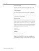
Table D.1 XM-121A Measuring Case Absolute with Accelerometer (100 mV/g)
Maximum Vibration Level Full Scale Setting Max High Frequency Peak Amplitude
mils pp micrometers pp 0.8Hz HPF 2Hz HPF 4Hz HPF 23.8Hz HPF (g pk)
5 125 0.0013 0.003 0.006 0.036 4
10 250 0.0026 0.006 0.012 0.072 4
20 500 0.007 0.02 0.04 0.24 4
50 12500 0.014 0.04 0.08 0.4 12
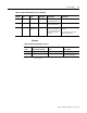
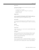
Table D.2 XM-121A Measuring Case Absolute with Velocimeter (100 mV/ips)
Maximum Vibration Level Full Scale Setting
mils pp micrometers pp 0.8Hz HPF 2Hz HPF 4Hz HPF 23.8Hz HPF
5 125 0.1
10 250 0.2
20 500 0.3
50 12500 1
Max Vibration Level (mils pp) Max High Freq Peak Amplitude (g) 19530 freq^2⁄×=
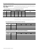
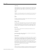
Table D.3 XM-121A Measuring Shaft Relative with Displacement Sensor (200 mV/mil)
Maximum Vibration Level Full Scale Setting
mils pp micrometers pp 0.8Hz HPF 2Hz HPF 4Hz HPF 23.8Hz HPF
5 125 1
10 250 2.5
15 375 4
20 500 5
50 12500 10