XM-121 Absolute Shaft Module User Guide Firmware Revision 5 1440-VLF02-01RA
Important User Information Solid state equipment has operational characteristics differing from those of electromechanical equipment. Safety Guidelines for the Application, Installation and Maintenance of Solid State Controls (publication SGI-1.1 available from your local Rockwell Automation sales office or online at http://literature.rockwellautomation.com) describes some important differences between solid state equipment and hardwired electromechanical devices.
Safety Approvals The following information applies when operating this equipment in hazardous locations. Informations sur l’utilisation de cet équipement en environnements dangereux. Products marked "CL I, DIV 2, GP A, B, C, D" are suitable for use in Class I Division 2 Groups A, B, C, D, Hazardous Locations and nonhazardous locations only. Each product is supplied with markings on the rating nameplate indicating the hazardous location temperature code.
Table of Contents Chapter 1 Introduction Introducing the Absolute Shaft Module . . . . . . . . . . . . . . . . . . . . . . . . . 1 Absolute Shaft Module Components . . . . . . . . . . . . . . . . . . . . . . . . . . . 2 Using this Manual. . . . . . . . . . . . . . . . . . . . . . . . . . . . . . . . . . . . . . . . . . . 3 Organization. . . . . . . . . . . . . . . . . . . . . . . . . . . . . . . . . . . . . . . . . . . . 3 Document Conventions . . . . . . . . . . . . . . . . . . . . . . . . . . . . . . . .
Table of Contents vi Alarm Parameters . . . . . . . . . . . . . . . . . . . . . . . . . . . . . . . . . . . . . . . . . . 55 Relay Parameters . . . . . . . . . . . . . . . . . . . . . . . . . . . . . . . . . . . . . . . . . . 59 4-20 mA Output Parameters . . . . . . . . . . . . . . . . . . . . . . . . . . . . . . . . . 63 Triggered Trend Parameters . . . . . . . . . . . . . . . . . . . . . . . . . . . . . . . . . 64 SU/CD Trend Parameters. . . . . . . . . . . . . . . . . . . . . . . . . . . . . . . . . .
Table of Contents vii Connection Object (Class ID 05H). . . . . . . . . . . . . . . . . . . . . . . . . . . . 99 Class Attributes . . . . . . . . . . . . . . . . . . . . . . . . . . . . . . . . . . . . . . . . 99 Instances . . . . . . . . . . . . . . . . . . . . . . . . . . . . . . . . . . . . . . . . . . . . 100 Instance Attributes. . . . . . . . . . . . . . . . . . . . . . . . . . . . . . . . . . . . . 100 Services . . . . . . . . . . . . . . . . . . . . . . . . . . . . . . . . . . . . . . . . . . . . .
Table of Contents viii Spectrum Waveform Measurement Object (Class ID 324H) . . . . . . 121 Class Attributes . . . . . . . . . . . . . . . . . . . . . . . . . . . . . . . . . . . . . . . 121 Instances. . . . . . . . . . . . . . . . . . . . . . . . . . . . . . . . . . . . . . . . . . . . . 122 Instance Attributes. . . . . . . . . . . . . . . . . . . . . . . . . . . . . . . . . . . . . 122 Services . . . . . . . . . . . . . . . . . . . . . . . . . . . . . . . . . . . . . . . . . . . . . .
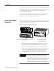
Chapter 1 Introduction This chapter provides an overview of the XM-121 Absolute Shaft module. It also discusses the components of the module. For information about Introducing the Absolute Shaft Module 1 Absolute Shaft Module Components 2 Using this Manual 3 IMPORTANT Introducing the Absolute Shaft Module See page This manual only describes how to install and use the XM-121 Absolute Shaft module.
2 Introduction It can operate stand-alone, or it can be deployed on a standard or dedicated DeviceNet network where it can provide real-time data and status information to other XM modules, PLCs, distributed control systems (DCS), and Condition Monitoring Systems. The Absolute Shaft module can be configured remotely via the DeviceNet network, or locally using a serial connection to a PC or laptop. Refer to Chapter 3 for a list of the configuration parameters.
Introduction Using this Manual 3 This manual introduces you to the XM-121 Absolute Shaft module. It is intended for anyone who installs, configures, or uses the XM-121 Absolute Shaft module. Organization To help you navigate through this manual, it is organized in chapters based on these tasks and topics. Chapter 1 "Introduction" contains an overview of this manual and the XM-121 module.
4 Introduction The XM-121 Absolute Shaft module is referred to as XM-121, Absolute Shaft module, device, or module throughout this manual. TIP EXAMPLE Publication GMSI10-UM014D-EN-P - May 2010 A tip indicates additional information which may be helpful. This convention presents an example.
Chapter 2 Installing the Absolute Shaft Module This chapter discusses how to install and wire the XM-121 Absolute Shaft module. It also describes the module indicators and the basic operations of the module, and provides instructions to install the Absolute Shaft firmware.
6 Installing the Absolute Shaft Module XM Installation Requirements This section describes wire, power, and grounding requirements for an XM system. Wiring Requirements Use solid or stranded wire. All wiring should meet the following specifications: • 14 to 22 AWG copper conductors without pretreatment; 8 AWG required for grounding the DIN rail for electromagnetic interference (emi) purposes • Recommended strip length 8 millimeters (0.
Installing the Absolute Shaft Module 7 Figure 2.
8 Installing the Absolute Shaft Module IMPORTANT See Application Technique "XM Power Supply Solutions", publication ICM-AP005A-EN-E, for guidance in architecting power supplies for XM systems. Grounding Requirements Use these grounding requirements to ensure safe electrical operating circumstances, and to help avoid potential emi and ground noise that can cause unfavorable operating conditions for your XM system. DIN Rail Grounding The XM modules make a chassis ground connection through the DIN rail.
Installing the Absolute Shaft Module 9 Figure 2.
10 Installing the Absolute Shaft Module Figure 2.3 DIN Rail Grounding Block Panel/Wall Mount Grounding The XM modules can also be mounted to a conductive mounting plate that is grounded. See Figure 2.5. Use the grounding screw hole provided on the terminal base to connect the mounting plate the Chassis terminals. Figure 2.
Installing the Absolute Shaft Module 11 Figure 2.5 Panel/Wall Mount Grounding 1 Power Supply 1 Power Supply 1 Use 14 AWG wire.
12 Installing the Absolute Shaft Module 24 V Common Grounding 24 V power to the XM modules must be grounded. When two or more power supplies power the XM system, ground the 24 V Commons at a single point, such as the ground bus bar. IMPORTANT IMPORTANT If it is not possible or practical to ground the -24Vdc supply, then it is possible for the system to be installed and operate ungrounded.
Installing the Absolute Shaft Module 13 Figure 2.6 Grounded DeviceNet V- at XM Module To Ground Bus ATTENTION Use of a separate DeviceNet power supply is not permitted. See Application Technique "XM Power Supply Solutions", publication ICM-AP005A-EN-E, for guidance in using XM with other DeviceNet products. For more information on the DeviceNet installation, refer to the ODVA Planning and Installation Manual - DeviceNet Cable System, which is available on the ODVA web site (http://www.odva.org).
14 Installing the Absolute Shaft Module The terminal base can be DIN rail or wall/panel mounted. Refer to the specific method of mounting below. ATTENTION The XM modules make a chassis ground connection through the DIN rail. Use zinc plated, yellow chromated steel DIN rail to assure proper grounding. Using other DIN rail materials (e.g. aluminum, plastic, etc.), which can corrode, oxidize or are poor conductors can result in improper or intermittent platform grounding.
Installing the Absolute Shaft Module 15 3. Rotate the terminal base onto the DIN rail with the top of the rail hooked under the lip on the rear of the terminal base. 4. Press down on the terminal base unit to lock the terminal base on the DIN rail. If the terminal base does not lock into place, use a screwdriver or similar device to open the locking tab, press down on the terminal base until flush with the DIN rail and release the locking tab to lock the base in place.
16 Installing the Absolute Shaft Module 5. Gently push the side connector into the side of the neighboring terminal base to complete the backplane connection. Panel/Wall Mounting Installation on a wall or panel consists of: • laying out the drilling points on the wall or panel • drilling the pilot holes for the mounting screws • installing the terminal base units and securing them to the wall or panel Use the following steps to install the terminal base on a wall or panel.
Installing the Absolute Shaft Module 17 1. Lay out the required points on the wall/panel as shown in the drilling dimension drawing below. Side Connector 2. Drill the necessary holes for the #6 self-tapping mounting screws. 3. Secure the terminal base unit using two #6 self-tapping screws. 4. To install another terminal base unit, retract the side connector into the base unit. Make sure it is fully retracted. 5. Position the terminal base unit up tight against the neighboring terminal base.
18 Installing the Absolute Shaft Module Figure 2.7 XM-940 Terminal Base Unit XM-940 (Cat. No. 1440-TB-A) Terminal Block Assignments The terminal block assignments and descriptions for the Absolute Shaft module are shown below. ATTENTION The following table applies only to the XM-121 module revision B01 (and later). Earlier revisions of the module do not support the wiring configuration of the Absolute Shaft module.
Installing the Absolute Shaft Module WARNING 19 EXPLOSION HAZARD Do not disconnect equipment unless power has been removed or the area is known to be nonhazardous. Do not disconnect connections to this equipment unless power has been removed or the area is known to be nonhazardous. Secure any external connections that mate to this equipment by using screws, sliding latches, threaded connectors, or other means provided with this product. Terminal Block Assignments No.
20 Installing the Absolute Shaft Module Terminal Block Assignments No.
Installing the Absolute Shaft Module 21 Connecting the Power Supply Power supplied to the module must be nominally 24 Vdc (±10%) and must be a Class 2 rated circuit. Wire the DC-input power supply to the terminal base unit as shown in Figure 2.8. Figure 2.
22 Installing the Absolute Shaft Module The alarms associated with the relay and whether the relay is normally de-energized (non-failsafe) or normally energized (failsafe) depends on the configuration of the module. Refer to Relay Parameters on page 59 for details. Table 2.1 shows the on-board relay connections for the module. IMPORTANT All XM relays are double pole. This means that each relay has two contacts in which each contact operates independently but identically.
Installing the Absolute Shaft Module 23 Figures 2.9 and 2.10 illustrate the behavior of the NC and NO terminals when the relay is wired for failsafe, alarm or nonalarm condition or non-failsafe, alarm or nonalarm condition. Figure 2.9 Relay Connection - Failsafe, Nonalarm Condition Non-failsafe, Alarm Condition Figure 2.10 Relay Connection - Failsafe, Alarm Condition Non-failsafe, Nonalarm Condition Alternate Relay Wiring Figures 2.11 and 2.
24 Installing the Absolute Shaft Module Figure 2.11 Relay Connection - Failsafe, Nonalarm Condition Non-failsafe, Alarm Condition Figure 2.12 Relay Connection - Failsafe, Alarm Condition Non-failsafe, Nonalarm Condition Connecting the Tachometer Signal The XM-121 provides a single tachometer input signal. The signal processing performed on the tachometer signal depends on the configuration of the module. See page 52 for a description of the tachometer parameters.
Installing the Absolute Shaft Module 25 Connecting a Magnetic Pickup Tachometer Figure 2.13 shows the wiring of a magnetic pickup tachometer to the terminal base unit. Figure 2.13 Magnetic Pickup Tachometer Signal Connection Connecting a Hall Effect Tachometer Sensor Figure 2.14 shows the wiring of a Hall Effect Tachometer Sensor, Cat. No. 44395, to the terminal base unit. Figure 2.
26 Installing the Absolute Shaft Module Connecting a Non-Contact Sensor to the Tachometer Signal Figure 2.15 shows the wiring of a non-contact sensor to the tachometer input signal. Figure 2.15 Non-Contact Sensor to Tachometer Signal Connection 4 18 Signal Common 20 21 31 Tach Input Signal -24V DC -24 SIG COM S hi e ld F lo a t i n g S h i el d Isolated Sensor Driver Connecting the Buffered Outputs The XM-121 provides buffered outputs of all transducer input signals.
Installing the Absolute Shaft Module 27 Figure 2.16 Buffered Output Connections IMPORTANT Applies only to XM-121 module revision B01 (and later). The voltage operating range of the buffered outputs must be configured to coincide with the corresponding transducer bias range. This operating range is configured by placing a jumper from terminal 5 (channel 1) and terminal 22 (channel 2) to either terminal 6 (Positive Buffer Bias) or terminal 21 (Buffer -), depending on the transducer. See Table 2.2.
28 Installing the Absolute Shaft Module The case mounted vibration sensor must be connected to channel 2. The Absolute Shaft module supports the following Allen-Bradley 9000 series sensors. Table 2.3 Supported Allen-Bradley 9000 Series Sensors Cat. No.
Installing the Absolute Shaft Module IMPORTANT 29 Make certain the IEPE Power parameter for channel 2 is enabled so power is provided to the 9000 sensor. Refer to Channel Parameters on page 46. Figure 2.
30 Installing the Absolute Shaft Module You may ground the cable shield at either end of the cable. Do not ground the shield at both ends. Recommended practice is to ground the cable shield at the terminal base and not at the transducer. Any convenient Chassis terminal may be used (see Terminal Block Assignments on page 18). ATTENTION The internal transducer power supply is providing power to the non-contact sensor connected to channel 1.
Installing the Absolute Shaft Module 31 Connecting the Remote Relay Reset Signal If you set the module relay to latching and the relay activates, the relay stays activated even when the condition that caused the alarm has ended. The remote relay reset signal enables you to reset your module relay remotely after you have corrected the alarm condition. This includes latched relays in the Expansion Relay module when it is attached to the XM-121.
32 Installing the Absolute Shaft Module A single switch contact can also be shared by multiple XM modules wired in parallel as shown in Figure 2.20. ATTENTION The relay reset connections may be different for different XM modules. Figure 2.20 applies only to the XM-121 module. Refer to the installation instructions for the module for its terminal assignments. Figure 2.
Installing the Absolute Shaft Module 33 Figure 2.21 Setpoint Multiplication Connection ATTENTION The Switch Input circuits are functionally isolated from other circuits. It is recommended that the Switch RTN signal be grounded at a signal point. Connect the Switch RTN signal to the XM terminal base (Chassis terminal) or directly to the DIN rail, or ground the signal at the switch or other equipment that is wired to the switch.
34 Installing the Absolute Shaft Module Figure 2.22 4-20 mA Output Connections - ATTENTION The 4-20 mA outputs are functionally isolated from other circuits. It is recommended that the outputs be grounded at a single point. Connect the 4-20 mA (-) to the XM terminal base (Chassis terminal) or directly to the DIN rail, or ground the signal at the other equipment in the 4-20 mA loop.
Installing the Absolute Shaft Module 35 • Mini-Connector - The mini-connector is located on top of the module, as shown in Figure 2.23. Figure 2.23 Mini-Connector mini-connector A special cable (Cat. No. 1440-SCDB9FXM2) is required for this connection. The connector that inserts into the PC is a DB-9 female connector, and the connector that inserts into the module is a USB Mini-B male connector.
36 Installing the Absolute Shaft Module Connect the DeviceNet cable to the terminal base unit as shown. Connect To Terminal Red Wire DNet V+ 26 (Optional - see note) White Wire CAN High 23 Bare Wire Shield (Chassis) 10 Blue Wire CAN Low 24 Black Wire DNet V- 27 IMPORTANT The DeviceNet power circuit through the XM module interconnect, which is rated at only 300 mA, is not intended or designed to power DeviceNet loads. Doing so could damage the module or terminal base.
Installing the Absolute Shaft Module 37 use the XM Serial Configuration Utility or RSNetWorx™ for DeviceNet (Version 3.0 or later) to set the network node address. Refer to the appropriate documentation for details. IMPORTANT Mounting the Module The baud rate for the XM-121 is set by way of "baud detection" (Autobaud) at power-up. The XM-121 mounts on the XM-940 terminal base unit, Cat. No. 1440-TB-A. We recommend that you mount the module after you have connected the wiring on the terminal base unit.
38 Installing the Absolute Shaft Module 1. Make certain the keyswitch (A) on the terminal base unit (C) is at position 1 as required for the module. 2. Make certain the side connector (B) is pushed all the way to the left. You cannot install the module unless the connector is fully extended. 3. Make sure that the pins on the bottom of the module are straight so they will align properly with the connector in the terminal base unit. 4.
Installing the Absolute Shaft Module 39 Figure 2.24 LED Indicators Module Indicators The following tables describe the states of the LED status indicators. Module Status (MS) Indicator Color State Description No color Off No power applied to the module. Green Flashing Red Module performing power-up self test. Flashing Module operating in Program Mode1. Solid Module operating in Run Mode2. Flashing • Application firmware is invalid or not loaded. Download firmware to the module.
40 Installing the Absolute Shaft Module Network Status (NS) Indicator Color State Description No color Off Module is not online. • Module is autobauding. • No power applied to the module, look at Module Status LED. Green Red 1 Flashing Module is online (DeviceNet) but no connections are currently established.1 Solid Module is online with connections currently established. Flashing One or more I/O connections are in the timed-out state.
Installing the Absolute Shaft Module 41 Relay Indicator Basic Operations Color State Description Red Off On-board relay is not activated. Solid On-board relay is activated. Powering Up the Module The module performs a self-test at power-up. The self-test includes an LED test and a device test. During the LED test, the indicators will be turned on independently and in sequence for approximately 0.25 seconds. The device test occurs after the LED test.
42 Installing the Absolute Shaft Module Figure 2.25 Reset Switch Press the Reset Switch to reset the relays The switch can be used to reset all latched relays in the module. This includes the relays in the Expansion Relay Module when it is attached to the XM-121 module. IMPORTANT Installing the XM-121 Absolute Shaft Firmware The Reset switch resets the relays only if the input is no longer in alarm or the condition that caused the alarm is no longer present.
Installing the Absolute Shaft Module 43 3. Connect the computer to the XM-121 module using the special serial cable. Refer to Serial Port Connection on page 34. 4. Power up the XM-121 module if you haven’t already done so, and start the XM Serial Configuration Utility program. Click the Start program, and then select Programs > Entek > XM > Serial Config Utility. TIP The Serial Configuration Utility defaults to the COM 1 serial port.
44 Installing the Absolute Shaft Module 6. Click the Module tab. Click this button to update the device with the Absolute Shaft firmware 7. In the Firmware Update group, click Update Firmware to initiate the firmware update. The Open dialog box appears. 8. Navigate to the Firmware directory on the CD and select the “xm12A.nvs” file. 9. Click Open to start the firmware update and click Yes to confirm. The Configuration Tool begins the update and shows its progress in the Progress dialog box. 10.
Chapter 3 Configuration Parameters This chapter provides a complete listing and description of the Absolute Shaft parameters. The parameters can be viewed and edited using the XM Serial Configuration Utility software and a personal computer. If the module is installed on a DeviceNet network, configuring can also be performed using a network configuration tool such as RSNetWorx (Version 3.0 or later). Refer to your configuration tool documentation for instructions on configuring a device.
46 Configuration Parameters Channel Parameters The channel parameters define the characteristics of the transducers you will be using with the Absolute Shaft module. Use the parameters to configure the transducer sensitivity, operating range, and power requirements. There are two instances of the channel parameters, one for each channel. The Absolute Shaft module requires the correct transducers. • Channel 1 must be connected to a non-contact probe measuring acceleration in mils or µm.
Configuration Parameters 47 Channel Parameters Parameter Name Description Values/Comments DC Bias Time Constant The time constant used for exponential averaging Seconds (low pass filtering) of the transducer DC bias measurement. The corner frequency for the low pass filter is 1 / (2π x DC Bias Time Constant). The greater the value entered, the longer the settling time of the measured value to a change in the input signal. See example table below.
48 Configuration Parameters Signal Processing Parameters The signal processing parameters determine the signal processing that will be performed on the input signals. Use these parameters to select the high and low pass filters. The signal processing parameters apply to both channels. Signal Processing Parameters Parameter Name Description Low HPF Frequency (EDS File only) Shows the corner frequency for the Low high pass filter option.
Configuration Parameters 49 Overall Measurement Parameters Parameter Name Description Values/Comments Signal Detection The measurement (or calculation) performed on the Options: RMS Calculated Peak input signal to produce the Overall Value. See Data Calculated Peak-to-Peak Parameters on page 69. True Peak True Peak-to-Peak • RMS - The Overall Value is the root mean squared (RMS) signal level of the input signal.
50 Configuration Parameters Overall Measurement Parameters Parameter Name Description Values/Comments Overall Damping Factor This parameter is used in conjunction with the Overall Time Constant to vary the characteristics of the response of the digital filter used in calculating the Overall Value. Enter a value from 0.707 to 1.0. An overall value for a measurement with a damping factor near 1.
Configuration Parameters TIP 51 The Waveform Period and the Number of Points must be configured such that the FMAX (Number of Points/(2.56 x waveform period)) is from 10 Hz to 9375 Hz. The table below shows some example settings for these parameters. Note that the Waveform Period may be rounded up to the next closes period due to available sampling rates. Combinations that will be rounded are indicated with an "x". Table 3.
52 Configuration Parameters Vector Measurement Parameters Parameter Name Description Values/Comments Q Enter the Q value for the Q filter. Q is the measure of the sharpness of a filter Enter a value from 1 to 200 Hz. Note: This value is used only when Q is selected as the tracking filter type. Important: The tracking filter bandwidth in Constant Q mode is limited between 0.5 and 15 Hz.
Configuration Parameters 53 Tachometer Transducer Parameters Tachometer Transducer Parameters Parameter Name Description Values/Comments Tachometer Name (XM Serial Configuration Utility only) A descriptive name to help identify the tachometer in Maximum 18 characters the XM Serial Configuration Utility software. Fault Low The minimum, or most negative, expected DC voltage from the transducer. Volts Note: A voltage reading outside this range constitutes a transducer fault.
54 Configuration Parameters Tachometer Signal Processing Parameters IMPORTANT The Absolute Shaft module requires the tachometer to track the machine speed (tracking filter) and to calculate the 1X measurements. If you are not using the tachometer channel, set the Pulses Per Revolution to zero. This will disable the tachometer measurement, and prevent the module from indicating a tachometer fault.
Configuration Parameters 55 Tachometer Signal Processing Parameters Parameter Name Description Values/Comments Trigger Hysteresis The amount of hysteresis around the trigger threshold. In Auto Trigger mode, the value entered is a percentage of the peak-to-peak input signal. This value can range from 0 to 50%. % in Auto Trigger mode Volt in Manual Trigger mode In Manual Trigger mode, the value entered is a voltage level.
56 Configuration Parameters Alarm Parameters Parameter Name Description Enable Enable/disable the selected alarm. Note: The Alarm Status is set to "Disarm" when the alarm is disabled. Condition Controls when the alarm should trigger. • Greater than - Triggers the alarm when the measurement value is greater than or equal to the Alert and Danger Threshold values. The Danger Threshold value must be greater than or equal to the Alert Threshold value for the trigger to occur.
Configuration Parameters 57 Alarm Parameters Parameter Name Description Values/Comments Alert Threshold (High) The threshold value for the alert (alarm) condition. Same measurement unit as Output Data Unit selection for the specified channel. Note: This parameter is the greater threshold value when Condition is set to "Inside Range" or "Outside Range." Danger Threshold (High) The threshold value for the danger (shutdown) condition.
58 Configuration Parameters Alarm Parameters Parameter Name Description Values/Comments Threshold Multiplier The action to take when the setpoint multiplier switch is closed (push button engaged or toggle switch flipped to on) and during the startup period once the switch is reopened. The module applies the multiplier to the alarm thresholds during this time to avoid false alarms at resonance frequencies. Enter any fractional value between 0 and 10.
Configuration Parameters Relay Parameters 59 The Relay parameters control the operation of the on-board relay, as well as the relays on the Expansion Relay (XM-441) module. Use these parameters to configure which alarm(s) the relay is associated with, as well as the behavior of the relay. IMPORTANT A relay can be defined, regardless of whether or not it is physically present. A non-physical relay is a virtual relay.
60 Configuration Parameters Relay Parameters Parameter Name Description XM Configuration EDS File Utility Latching Latching Option XM Configuration EDS File Utility Logic XM Configuration EDS File Utility Alarm A/B XM Configuration Utility EDS File Check means latching (relay must be explicitly reset) Latching Clear means non-latching (relay is reset once the alarm condition has passed) Nonlatching Enter a value from 0 to 25.
Configuration Parameters 61 Relay Parameters Parameter Name Description Options/Comments Sets the alarm conditions that will cause the relay to Options: Normal Danger activate. You can select more than one. Xdcr Fault Tacho Fault • Normal The current measurement is not within Alarm Levels Alert excess of any alarm thresholds. Disarm • Alert - The current measurement is in excess of Module Fault the alert level threshold(s) but not in excess of the danger level threshold(s).
62 Configuration Parameters Relay Parameters Parameter Name Description XM Configuration EDS File Utility Failsafe Relay Failsafe Option Determines whether the relay is failsafe or non-failsafe. Failsafe operation means that when in alarm, the relay contacts are in their "normal," de-energized, or "shelf-state" positions. In other words, normally closed relays are closed in alarm, and normally open relays are open in alarm. With failsafe operation, a power failure equals an alarm.
Configuration Parameters 4-20 mA Output Parameters 63 The 4-20 mA output parameters define the characteristics of the two 4-20 mA output signals. The parameters are the same for each output. 4-20 mA Output Parameters Parameter Name Description Options/Comments Enable Enables/disables the 4-20 mA output. XM Configuration Utility EDS File Check to enable Enabled Clear to disable Disabled Measurement Sets the type of measurement and the channel that the 4-20 mA output signal will track.
64 Configuration Parameters Triggered Trend Parameters The Absolute Shaft module can collect a triggered trend. A triggered trend is a time-based trend that is collected when a relay is activated, or the module receives a trigger event. Once the triggered trend is configured, the XM module continuously monitors the trended measurements. When a trigger occurs, the XM module collects additional data as specified by the Post Trigger parameter.
Configuration Parameters 65 Triggered Trend Parameters Parameter Name Description Values/Comments Relay Number Sets the relay that triggers the trend to be collected. None means that the trend can only be triggered manually or by a trigger event (for example, XM-440). Relay Numbers 1 through 5 are either relays on the Expansion Relay module when it’s connected to the module or virtual relays. Note: The relay must be enabled. Refer to Relay Parameters on page 59.
66 Configuration Parameters SU/CD Trend Parameters The Absolute Shaft module can collect startup or coast-down trend data when the machine speed passes into a defined speed range. A tachometer input is required to collect the startup/coast-down trend. The XM module collects a startup trend when the machine speed rises through the Minimum Speed + 8 RPM, and stops when the machine speed crosses either the Minimum Speed or the Maximum Speed. The module collects data only when machine speed is increasing.
Configuration Parameters 67 SU/CD Trend Parameters Parameter Name Description Values/Comments Latch Enable Determines whether the startup/coast-down trend is Check means latched Clear means unlatched latched or unlatched. Latched means that subsequent startup/coast-down trends are ignored after the initial startup/coast-down. This prevents the trend data from being overwritten with new data until the trigger is manually reset (click Reset Trigger button).
68 Configuration Parameters SU/CD Trend Parameters Parameter Name Description Values/Comments Status Shows the status of the trend data. Possible status values: • Not collected - No trend data is currently collected. • Collecting - A trigger has occurred and data is being collected. • Collected - A trend has been saved to the buffer and is available to view and upload. View Trend Data Displays a plot of the collected trend data. Reset Trigger Resets the trigger if Latch enabled is selected.
Configuration Parameters 69 I/O Data Parameters Parameter Name Description Values/Comments Poll Size Sets the size (number of bytes) of the Poll response The minimum size is 4 bytes and the message. Decreasing the maximum size will truncate maximum size is 124 bytes. data from the end of the Assembly structure. Important: If you set the Poll Output to "Custom Assembly," the poll size is automatically set to the actual size of the customized Poll response.
70 Configuration Parameters Monitor Data Parameters Monitor Data Parameters Parameter Name Description Overall Shows the measured overall value for the calculated shaft absolute, non-contact probe (Channel 1), and vibration sensor on the case (Channel 2). Magnitude Shows the magnitude shaft absolute vibration value. Requirement: The tachometer must be enabled (Pulses Per Revolution Shows the shaft absolute vibration phase value. set to 1 or more), and a tachometer signal must be present.
Configuration Parameters 71 Alarm and Relay Status Parameters Alarm and Relay Status Parameters Parameter Name Description Values/Comments Alarm Status States the current status of the alarm. Possible status values: • Normal - The alarm is enabled, the device is in Run mode, there is no transducer fault, and the current measurement is not within the Alert or Danger Threshold value(s).
72 Configuration Parameters Device Mode Parameters The Device Mode parameters are used to control the functions and the behavior of the device. IMPORTANT The XM Serial Configuration Utility handles these parameters automatically and transparently to the user. Device Mode Parameters Parameter Name Description Values/Comments Device Mode Sets the current operation mode of the device. Refer to Changing Operation Modes on page 81 for more information.
Appendix A Specifications The Appendix lists the technical specifications for the Absolute Shaft module. XM-121 Absolute Shaft Technical Specifications Product Feature Specification Communications DeviceNet Standard DeviceNet protocol for all functions NOTE: The XM-121 uses only the DeviceNet protocol, not power. Module power is provided independently.
74 Specifications XM-121 Absolute Shaft Technical Specifications Product Feature Specification Inputs Channel 1 Eddy current transducer Supports 5, 8, & 11 mm Allen-Bradley 2100 Series and Bently Nevada 3300 XL Series probes Channel 2 Case Mounted Sensor Supports the following sensors: 9000A Gen. Purpose Accel 9100VO Vel Output Accel 9100 CSA Gen Purpose Accel 9100T High Temp Accel Transducer Power Constant voltage (-24V dc)* Constant current (4.
Specifications 75 XM-121 Absolute Shaft Technical Specifications Product Feature Specification Outputs 4-20 mA Outputs Each output is independently programmed to represent any measured parameter, from either channel Two isolated outputs 300 ohm max load Buffered Outputs 1 active buffer per vibration input channel Resistive buffer for tachometer Indicators 7 LEDs Module Status - red/green Network Status - red/green Channel 1 Status - yellow/red Channel 2 Status - yellow/red Tachometer Status - yellow/red
76 Specifications XM-121 Absolute Shaft Technical Specifications Product Feature Specification Measured Parameters Shaft Relative Overall (Eddy Current Probe) 1x Magnitude 1x Phase Gap (volts) Case Absolute Output units selectable as either Velocity or (Velocity or Accelerometer) Displacement Overall 1X Magnitude 1X Phase Bias (volts) Shaft Absolute Overall (Calculated) 1X Magnitude 1X Phase Speed RPM Alarms Number 9 alarm and danger pairs Shaft Absolute Overall Shaft Absolute 1X Magnitude Shaft Relativ
Specifications 77 XM-121 Absolute Shaft Technical Specifications Product Feature Specification Relays Number Single on-board relay, two sets of contacts DPDT (2 Form C) Four additional relays when interconnected to an XM-441 Expansion Relay module, or Four virtual relays whose status can be used by remote Control Systems or the XM-440 Master Relay module On-board Relay Rating Maximum Voltage: 120V dc, 125V ac Maximum Current: 3.5 A* Minimum Current: 0 Maximum Power: 60 W, 62.
78 Specifications XM-121 Absolute Shaft Technical Specifications Product Feature Specification Non-Volatile Configuration A copy of the module configuration is retained in non-volatile memory from where it is loaded upon power up*. *The configuration stored in non-volatile memory can be deleted only by a module-reset command sent via the serial interface, using the Serial Configuration Utility, or via DeviceNet from any compliant software application.
Specifications 79 XM-121 Absolute Shaft Technical Specifications Product Feature Approvals (when product or packaging is marked) Specification UL UL Listed for Ordinary Locations UL UL Listed for Class I, Division 2 Group A, B, C, and D Hazardous Locations CSA CSA Certified Process Control Equipment CSA CSA Certified Process Control Equipment for Class I, Division 2 Group A, B, C, and D Hazardous Locations EEX* European Union 94/9/EEC ATEX Directive, compliant with EN 50021; Potentially Explosiv
80 Specifications Publication GMSI10-UM014D-EN-P - May 2010
Appendix B DeviceNet Information Electronic Data Sheets Electronic Data Sheet (EDS) files are simple text files used by network configuration tools such as RSNetWorx (Version 3.0 or later) to help you identify products and easily commission them on a network. The EDS files describe a product’s device type, product revision, and configurable parameters on a DeviceNet network. The EDS files for the XM modules are installed on your computer with the XM configuration software.
82 DeviceNet Information Transition to Program Mode Parameter values can only be downloaded to an XM module while the module is in Program mode. Any attempt to download a parameter value while the module is in Run mode will result in a Device State Conflict error. To transition an XM module from Run mode to Program mode on a DeviceNet network, set the Device Mode parameter to "Program mode" and click Apply.
DeviceNet Information 83 The table below defines services supported by the XM modules. The table includes the service codes, classes, instances, and attributes by their appropriate hexadecimal codes. Use the Class Instance Editor in RSNetWorx to execute these services, as illustrated in the example below.
84 DeviceNet Information Example To save the configuration parameters to the non-volatile memory (EEPROM), fill in the Class Instance Editor as shown below. Clear Send the attribute ID and then enter the Class (320 hex) and Instance (1) Select the Save service code Click Execute to initiate the action Invalid Configuration Errors A Start or Save service request to an XM module may return an Invalid Device Configuration error when there is a conflict amongst the configuration settings.
DeviceNet Information 85 Additional Error Codes returned with the Invalid Device Configuration Error (0xD0) Absolute Shaft I/O Message Formats Error Code (Hex) Description 0A Too many alarms associated with a single measurement. 0B Invalid node address in the alarm list. 0C Too many alarms in the alarm list. Or, no alarms in the alarm list. 0D Alarm levels cannot be zero for alarms that are enabled. 0E Too many slaves in the scanner’s input data table.
86 DeviceNet Information The Poll response data can also be requested explicitly through Assembly Object (Class ID 0x4), Instance 101 (0x65), Data Attribute (3). The following table shows the static data format of Assembly instance 101.
DeviceNet Information 87 XM Status Values The following tables describe the XM Status values that are included in the COS messages.
88 DeviceNet Information Figure B.1 Bit-Strobe Command The XM modules use the bit received in a Bit-Strobe connection as a trigger event. When the bit number corresponding to the XM module’s node address is set, the XM module will collect the triggered trend data. Note that the XM modules do not send data in the Bit-Strobe response. ADR for XM Modules Automatic Device Replacement (ADR) is a feature of an Allen-Bradley DeviceNet scanner.
DeviceNet Information 89 • The ADR scanner can not download the configuration data to an XM module if the module has a saved configuration in its non-volatile memory. This happens because the saved configuration is restored and the module enters Run mode when the power is cycled. (Configuration parameters cannot be downloaded while an XM module is in Run mode.) XM modules must be in Program mode for the ADR configuration to be downloaded and this occurs only when there is no saved configuration.
90 DeviceNet Information – All SU/CD Trend related parameters (see page 66) – Custom Assembly structure (see page 68) • The ADR and trigger group functions cannot be used together. A module can have only one primary master so a module cannot be both configured for ADR and included in a trigger group. The ADR scanner must be the primary master for the modules configured for ADR. The XM-440 Master Relay module must be the primary master for modules included in a trigger group.
Appendix C DeviceNet Objects Appendix C provides information on the DeviceNet objects supported by the Absolute Shaft module.
92 DeviceNet Objects The Identity Object provides identification and general information about the device. Identity Object (Class ID 01H) Class Attributes The Identity Object provides no class attributes. Instance Attributes Table C.
DeviceNet Objects 93 Table C.2 Identity Object Status Bit Name Description 4 Boot Program Vendor-specific, indicates that the boot program is running. The Main Application must be corrupt or missing. 5-7 Vendor-specific, not implemented 8 Minor Recoverable Fault Set whenever there is a transducer or tachometer fault. 9 Minor Unrecoverable Fault Not implemented 10 Major Recoverable Fault Set when the module detects a major problem that the user may be able to recover from.
94 DeviceNet Objects The DeviceNet Object is used to provide the configuration and status of a physical attachment to DeviceNet. DeviceNet Object (Class ID 03H) Class Attributes Table C.4 DeviceNet Object Class Attributes Attr ID Access Rule Name Data Type Default Value 1 Get Revision UINT 2 Instance Attributes Table C.
DeviceNet Objects 95 rate detection instead. This means that the module will determine the network baud rate by listening for network traffic before attempting to go online. Services Table C.6 DeviceNet Object Services Service Code Class/Instance Usage Name 0Eh Class/Instance Get_Attribute_Single 10h Instance Set_Attribute_Single1 4Bh Instance Allocate_Master/Slave_Connetion_Set 4Ch Instance Release_Group_2_Identifier_Set 1 Attributes can only be set while the device is in Program Mode.
96 DeviceNet Objects Instances Table C.8 Assembly Object Instances Instance Name Type Description 100 Default COS Message Input Alarm and Relay Status values 101 Default Poll Response Message Input Measurement values 199 Alternate Dynamic Poll Response Message Input User configurable measurement values and configuration parameters Instance Attributes Table C.
DeviceNet Objects 97 Assembly Instance Attribute Data Format Instance 100 - Alarm and Relay Status This assembly is sent using COS messaging when any of the Alarm or Relay Status values change. Table C.
98 DeviceNet Objects Instance 199 - Dynamic Assembly This Assembly instance can be created and configured with the XM Serial Configuration Utility or RSMACC Enterprise Online Configuration Utility. Using the configuration software, you determine the format of the data. This assembly instance can be selected to be sent in response to an I/O Poll request from a Master. The dynamic Assembly can include all of the measurement values included in Assembly instance 101.
DeviceNet Objects 99 Table C.12 Instance 199 Component Mapping EPATH (where ii = instance number) Class Name Class Number Instance Number Attribute Name Attribute Number Data Type 21 0F 00 24 ii 30 01 Param 0Fh 12 - 16 Parameter Value (Alarm Identifier B) 1 USINT 21 23 03 24 ii 30 0C Relay 323h 1-5 Logic 12 USINT 21 23 03 24 ii 30 0E Relay 323h 1-5 Relay Installed 14 BOOL The dynamic Assembly instance must be instantiated with a call to the class level Create service.
100 DeviceNet Objects Instances Table C.14 Connection Object Instances Instance Description 1 Explicit Message Connection for pre-defined connection set 2 I/O Poll Connection 3 I/O Strobe Connection 4 I/O COS (change of state) Connection 11 - 17 Explicit Message Connection Instance Attributes Table C.15 Connection Object Instance Attributes Attr ID Access Rule Name Data Type Description 1 Get State USINT State of the object.
DeviceNet Objects 101 Table C.15 Connection Object Instance Attributes Attr ID Access Rule 15 Name Data Type Description Get Consumed Connection Path Length UINT Number of bytes in the consumed_connection_path attribute. 16 Get Consumed Connection Path Array of USINT Specifies the Application Object(s) that are to receive the data consumed by this Connection Object. See DeviceNet Specification Volume 1 Appendix I.
102 DeviceNet Objects Instance Attributes Table C.18 Discrete Input Object Instance Attributes Attr ID Access Rule Name Data Type Description Semantics 3 Get Value BOOL Setpoint Multiplier 0 = Off 1 = On 199 Set Backdoor Service USINT Setting this attribute is equivalent to requesting the specified service. Set to one of the following values to perform the specified service: 0x32 = Open 0x33 = Close Services Table C.
DeviceNet Objects 103 Class Attributes Table C.20 Parameter Object Class Attributes Attr ID Access Rule Name Data Type Description Semantics 2 Get Max Instance UINT Maximum instance number of an object in this class. Total number of parameter object instances. 8 Get Parameter Class WORD Descriptor Bits that describe the parameter. Bit 0 Supports Parameter Instances Bit 1 Supports Full Attrib. Bit 2 Must do non-volatile store Bit 3 Params in non-volatile 9 Get Config.
104 DeviceNet Objects Table C.21 Parameter Object Instances Instance Read Only 6 Name Data Type Valid Values Default Value No 4-20 mA Output 2 Measurement Identifier USINT 0 = CH 1 SR Overall 1 = CH 2 CA Overall 2 = CH 1 SR 1X Mag. 3 = CH 2 CA 1X Mag. 4 = Shaft Absolute Overall 5 = Shaft Absolute 1X Mag.
DeviceNet Objects 105 Table C.
106 DeviceNet Objects Table C.
DeviceNet Objects 107 Table C.22 Parameter Object Instance Attributes Attr ID Access Rule Name Data Type Description Semantics 4 Get Descriptor WORD Description of Parameter Bit 0 = Settable Path support Bit 1 = Enum Strings support Bit 2 = Scaling support Bit 3 = Scaling Links support Bit 4 = Read Only Bit 5 = Monitor Bit 6 = Ext. Prec. scaling 5 Get Data Type EPATH Data Type Code See DeviceNet Specification Volume 1 Appendix J, Section J-6.
108 DeviceNet Objects Instances A module provides only a single instance (instance 1) of the Acknowledge Handler Object. This instance is associated with instance 4 of the Connection Object, the slave COS connection to a higher level master. Instance Attributes Table C.
DeviceNet Objects 109 Instances There are 9 instances of this object. Each instance is permanently associated with a different measurement. Table C.27 Alarm Object Instances Instance Number Associated Measurement 1 CH 1 Shaft Relative Overall 2 CH 2 Case Absolute Overall 3 CH 1 DC Bias 4 CH 2 DC Bias 5 CH 1 Shaft Relative 1X Magnitude 6 CH 2 Case Absolute 1X Magnitude 7 Shaft Absolute Overall 8 Shaft Absolute 1X Magnitude 9 Speed Instance Attributes Table C.
110 DeviceNet Objects Table C.28 Alarm Object Instance Attributes Attr ID Access Rule 8 Name Data Type Description Get/Set Alert Threshold (High) REAL The threshold value for the alert (alarm) condition (greater threshold for range types). 9 Get/Set Danger Threshold (High) REAL The threshold value for the danger (shutdown) condition (greater threshold for range types).
DeviceNet Objects 111 Table C.28 Alarm Object Instance Attributes Attr ID Access Rule Name Data Type Description 17 Get/Set Speed Range Low REAL CPM Indicates the lesser threshold of the machine (Must be less than Speed speed range for which the Range High) alarm is enabled (disabled at lesser speeds). 18 Get/Set Name STRING2 A name to help identify this alarm. 20 Get/Set Inhibit Tach Fault BOOL Determines whether the Tach Fault status is prohibited during the startup period.
112 DeviceNet Objects Instances There are 2 instances of this object. Table C.30 Channel Object Instances Instance Associated Channel 1 Shaft Relative Channel 2 Case Absolute Channel Instance Attributes Table C.31 Channel Object Instance Attributes Attr ID Access Rule 3 Get/Set Name Data Type Description Semantics Output Data Units1 ENGUNIT The data units of the signal resulting from the signal processing performed in the channel. See DeviceNet Specification Volume 1 Appendix K.
DeviceNet Objects 113 Table C.31 Channel Object Instance Attributes Attr ID Access Rule Name Data Type Description Semantics 10 Get/Set Full Scale REAL The maximum signal expected to be processed by the channel. Volts peak Setting the Full Scale to a greater value allows the channel to handle greater input signals without saturating or clipping. Setting the Full Scale to a lesser value allows the signal to be measured with greater resolution.
114 DeviceNet Objects Services Table C.32 Channel Object Services Service Code Class/Instance Usage Name Description 0Eh Instance Get_Attribute_Single Returns a single attribute. 10h Instance Set_Attribute_Single Sets a single attribute.1 4Bh Instance Auto_Range Automatically determines the optimal analog hardware range and sets the Full Scale value accordingly.1 1 Attributes can only be set while the device is in Program Mode.
DeviceNet Objects 115 Table C.34 Auto_Range Response Parameters Name Data Type Description of Response Parameters Full Scale REAL The new Full Scale value. Device Mode Object (Class ID 320H) Semantics of Values Specifies the maximum signal level expected to be processes by the channel. This value is used to determine the analog hardware range when the hardware supports programmable gain settings.
116 DeviceNet Objects Setting the Device Mode attribute to "1" (RUN) is equivalent to executing the Start service. Setting the Device Mode attribute to "2" (PROGRAM) is equivalent to executing the Stop service. Services Table C.36 Device Mode Object Services Service Code Class/Instance Usage Name Description 0Eh Instance Get_Attribute_Single Return the value of a single attribute. 10h Instance Set_Attribute_Single Set the value of a single attribute.
DeviceNet Objects 117 Instances There are 3 instances of this object. Table C.37 Overall Measurement Object Instances Instance Description 1 Channel 1 Shaft Relative Overall 2 Channel 2 Case Absolute Overall 3 Shaft Absolute Overall Instance Attributes Table C.
118 DeviceNet Objects Table C.38 Overall Measurement Object Instance Attributes Attr ID Access Rule Name Data Type Description Semantics 7 Get/Set Time Constant1 REAL The detection time constant associated with the output smoothing filter (for the RMS and DC meters) or the decay rate of the peak meters. Must be greater than zero. For RMS type measurements, the Time Constant attribute specifies the 3-db bandwidth for the digital filtering used to calculate the Overall Value.
DeviceNet Objects 119 Services Table C.39 Overall Measurement Object Services Service Code Class/Instance Usage Name Description 0Eh Instance Get_Attribute_Single Returns a single attribute. 10h Instance Set_Attribute_Single Sets a single attribute.1 1 Attributes can only be set while the device is in Program Mode. See the description of the Device Mode Object for more information. The Relay Object models a relay (actual or virtual).
120 DeviceNet Objects Instance Attributes Table C.41 Relay Object Instance Attributes Attr ID Access Rule Name Data Type Description Semantics 3 Get Relay Status BOOL The current status of the relay. 0 = Off 1 = On 4 Get/Set Relay Enable BOOL Indicates whether this relay object is enabled. 0 = Disabled 1 = Enabled 5 Get/Set Latch Enable BOOL Indicates whether this relay latches (requires a reset command to deactivate).
DeviceNet Objects 121 Table C.41 Relay Object Instance Attributes Attr ID Access Rule 11 Name Data Type Description Semantics Get/Set Alarm Identifier B EPATH Identifies the second alarm status the relay monitors. See Parameter Object instances 12 to 16. 12 Get/Set Logic USINT Indicates the number of associated alarms that must have a status value specified by Alarm Level in order to activate the relay.
122 DeviceNet Objects Instances There are 2 instances of this object. Table C.43 Spectrum Waveform Measurement Object Instances Instance Description 1 Channel 1 Shaft Relative Overall 2 Channel 2 Case Absolute Overall Instance Attributes Table C.44 Spectrum Waveform Measurement Object Instance Attributes Attr ID Access Rule Name Data Type Description Semantics 3 Get Status BOOL Indicates if a fault or alarm has occurred. 0 = Operating without alarms or faults.
DeviceNet Objects 123 Table C.45 Spectrum Waveform Measurement Object Services Service Code Class/Instance Usage Name Description 10h Instance Set_Attribute_Single Sets a single attribute.1 4Ch Instance Get_Waveform_Chunk Upload a portion of the current Waveform data. 4Eh Instance Get_Stored_Waveform_ Chunk Upload a portion of the stored Waveform data. 1 Attributes can only be set while the device is in Program Mode. See the description of the Device Mode Object for more information.
124 DeviceNet Objects Measurement Object on the input signal. The Waveform Data array values are normalized and must be converted to floating point to obtain the true values. Table C.46 Waveform Data Structure Byte (DWORD) offset within structure Structure Member Data Type Description 0 (0) Number of Waveform Points UDINT Number of points in the waveform data. This should be equal to the Number of Waveform Points attribute setting.
DeviceNet Objects 125 The Get_Waveform_Chunk service uses the following request and response parameters. Table C.47 Get_Waveform_Chunk Request Parameters Name Data Type Initial DWORD Offset UINT Number of DWORDs USINT Description of Request Parameters Semantics of Values The offset of the first 32-bit value within the data structure to be returned. 0 <= offset < size of the data structure in DWORDs.
126 DeviceNet Objects Instance Attributes Table C.49 Speed Measurement Object Instance Attributes Attr ID Access Rule Name Data Type Description Semantics 3 Get Speed Value REAL The measured speed value. CPM 4 Get Status BOOL Indicates if a fault or alarm has occurred. 0 = Operating without alarms or faults. 1 = Alarm or fault condition exists. The Speed Value attribute may not represent the actual field value.
DeviceNet Objects Tachometer Channel Object (Class ID 326H) 127 The Tachometer Channel Object models "front end" processing performed on a tachometer signal before specific measurements are performed. Class Attributes The Tachometer Channel Object provides no class attributes. Instance Attributes Table C.
128 DeviceNet Objects Services Table C.52 Tachometer Channel Object Services Service Code Class/Instance Usage Name Description 0Eh Instance Get_Attribute_Single Returns a single attribute. 10h Instance Set_Attribute_Single Sets a single attribute.1 1 Transducer Object (Class ID 328H) Attributes can only be set while the device is in Program Mode. See the description of the Device Mode Object for more information. The Transducer Object models a transducer.
DeviceNet Objects 129 Instance Attributes Table C.54 Transducer Object Instance Attributes Attr ID Access Rule Name Data Type Description 3 Get DC Bias REAL The measured average DC Volts bias of the transducer signal in volts. 4 Get Status BOOL 0 = No fault Indicates whether a 1 = A transducer fault exists transducer fault exists (the measured DC Bias is outside the range specified by Fault High and Low).
130 DeviceNet Objects Services Table C.55 Transducer Object Services Service Code Class/Instance Usage Name Description 0Eh Instance Get_Attribute_Single Returns a single attribute. 10h Instance Set_Attribute_Single Sets a single attribute.1 1 Vector Measurement Object (Class ID 329H) Attributes can only be set while the device is in Program Mode. See the description of the Device Mode Object for more information.
DeviceNet Objects 131 Instance Attributes Table C.57 Vector Measurement Object Instance Attributes Attr ID Access Rule 3 Name Data Type Description Semantics Get Magnitude Value REAL The measured magnitude value. 4 Get Phase Value REAL The measured phase value. Degrees 5 Get Status BOOL Indicates if a fault or alarm has occurred. 0 = Operating without alarms of faults. 1 = Alarm or fault condition exists. The Value attributes may not represent the actual field value.
132 DeviceNet Objects Services Table C.58 Vector Measurement Object Services Service Code Class/Instance Usage Name Description 0Eh Instance Get_Attribute_Single Returns a single attribute. 10h Instance Set_Attribute_Single Sets a single attribute.1 1 4-20 mA Output Object (Class ID 32AH) Attributes can only be set while the device is in Program Mode. See the description of the Device Mode Object for more information.
DeviceNet Objects 133 Table C.59 4-20 mA Output Object Instance Attributes Attr ID Access Rule Name Data Type Description 5 Get/Set Max Range REAL The measured value associated with 20 mA. 6 Get/Set Min Range REAL The measured value associated with 4 mA. 7 Get/Set Measurement Identifier Path EPATH Identifies the class, instance, and attribute of a measurement value that this 4-20 mA output is tracking. Semantics See Parameter Object Instances 5 and 6.
134 DeviceNet Objects Publication GMSI10-UM014D-EN-P - May 2010
Appendix D Guidelines for Setting the Full Scale Value Appendix D provides tables to help you determine the optimal value to use for the Full Scale setting in the XM-121 Absolute Shaft module. The signal conditioning circuitry in the module adjusts its dynamic range based upon the value entered in this setting. The full scale value is a voltage level that is dependent upon your monitoring application and other XM configuration settings.
136 Guidelines for Setting the Full Scale Value XM-121 Absolute Shaft Full Scale Tables Use the following tables to help you determine the optimal Full Scale value for the XM-121 Absolute Shaft module. Refer to the table that corresponds to the units of vibration that will be used for monitoring. Table D.1 XM-121A Measuring Case Absolute with Accelerometer (100 mV/g) Maximum Vibration Level Full Scale Setting Max High Frequency Peak Amplitude mils pp micrometers pp 0.8Hz HPF 2Hz HPF 4Hz HPF 23.
Guidelines for Setting the Full Scale Value Example on Using Table 137 The following example shows you how to use the Full Scale table to determine the optimal Full Scale value. EXAMPLE Application: XM-121 Absolute Shaft module with 100 mV/g accelerometer Units used for monitoring: case absolute, ips or mils High pass filter: 4 Hz Maximum vibration level: 8 mils pp To determine the optimal Full Scale value, follow these steps. 1. Refer to Table D.
138 Guidelines for Setting the Full Scale Value Publication GMSI10-UM014D-EN-P - May 2010
Glossary alarm An alarm alerts you to a change in a measurement. For example, an alarm can notify you when the measured vibration level for a machine exceeds a pre-defined value. Automatic Device Replacement (ADR) A means for replacing a malfunctioning device with a new unit, and having the device configuration data set automatically. The ADR scanner uploads and stores a device’s configuration.
Glossary 140 Change of State (COS) DeviceNet communications method in which the XM module sends data based on detection of any changed value within the input data (alarm or relay status). current configuration The current configuration is the most recently loaded set of configuration parameters in the XM module’s memory. When power is cycled, the current configuration is loaded with either the saved configuration (in EEPROM) or the factory defaults (if there is no saved configuration).
Glossary 141 Help window A window that contains help topics that describe the operation of a program. These topics may include: • • • • An explanation of a command. A description of the controls in a dialog box or property page. Instructions for a task. Definition of a term. high pass filter A filter that excludes all frequencies below a defined frequency. It allows, or passes, frequencies above the defined frequency.
Glossary 142 online help Online help allows you to get help for your program on the computer screen by pressing F1. The help that appears in the Help window is context sensitive, which means that the help is related to what you are currently doing in the program. orders Multiples of the operating speed of a piece of equipment. The first order is the operating speed. The second order is two times the operating speed, and so on.
Glossary 143 RMS (square root of the mean of the square of the values) are the most common methods of signal detection. slave device A device that receives and responds to messages from a Master device but does not initiate communication. Slave devices include the XM measurement modules, such as the XM-120 Dynamic Measurement module and the XM-320 Position module.
Glossary 144 XM configuration XM configuration is a collection of user-defined parameters for XM modules. XM Serial Configuration Utility software XM Serial Configuration Utility software is a tool for monitoring and configuring XM modules. It can be run on computers running Windows 2000 service pack 2, Windows NT 4.0 service pack 6, or Windows XP operating systems.
Index Numerics 24V common grounding requirements 12 4-20mA Output Object 132 4-20mA output parameters 63 Enable 63 Max Range 63 Measurement 63 Min Range 63 4-20mA outputs, wiring 33 A Acknowledge Handler Object 107 Alarm Object 108 alarm parameters 55 Alarm 55 Alert Threshold (High) 57 Alert Threshold (Low) 57 Condition 56 Danger Threshold (High) 57 Danger Threshold (Low) 57 Enable 56 Hysteresis 57 Inhibit Tachometer Fault 58 Name 55 Speed Range Enable 58 Speed Range High 58 Speed Range Low 58 Startup Per
146 Index data parameters (continued) Relay Status 71 Speed Status 70 Speed Value 70 Transducer 3 Status 70 Transducer Fault 70 Transducer Status 70 Xdcr DC Bias 70 description configuration parameters 45 XM-121 Absolute Shaft module 2 XM-441 module 2 XM-940 terminal base 2 Device Mode Object 115 Device Mode parameter 72, 81 Device Mode parameters Autobaud 72 Device Mode 72, 81 DeviceNet connection baud rate 37 node address 36 wiring 35 DeviceNet grounding requirements 12 DeviceNet information automatic d
Index installation requirements grounding 8 power 6 wiring 6 interconnecting terminal base units 15 introduction 1 invalid device configuration errors 84 K keyswitch 37 M Module Status (MS) indicator 39 mounting terminal base unit on DIN rail 13, 14 terminal base unit on panel/walll 16 XM-121 module on terminal base 37 N Network Status (NS) indicator 40 node address 36 normally closed relay contacts 21 normally open relay contacts 21 O operating mode program mode 39, 81 run mode 39, 81 Overall Measurem
148 Index SU/CD trend parameters 66 Enable SU/CD Trend 66 Latch Enable 67 Maximum Speed 67 Maximum Trend Span 67 Minimum Speed 67 Number of Records 66 Record Interval 67 Reset Trigger 68 Select Measurements 66 Status 68 View Trend Data 68 switch input grounding requirements 13 T Tachometer Channel Object 127 tachometer parameters 52 Auto Trigger 54 DC Bias Time Constant 53 Fault High 53 Fault Low 53 Fault Time-Out 54 Pulses Per Revolution 54 Speed Multiplier 54 Tach Multiplier 54 Tachometer Name 53 Trigg
Index XM-121 Absolute Shaft Module (continued) reset switch 41 self-test 41 specifications 73 wiring requirements 6 149 XM-441 Expansion Relay Module 2, 42, 59 XM-940 terminal base description 2 mounting 13 wiring 17 Publication GMSI10-UM014D-EN-P - May 2010
Rockwell Automation Support Rockwell Automation provides technical information on the Web to assist you in using its products. At http://support.rockwellautomation.com, you can find technical manuals, a knowledge base of FAQs, technical and application notes, sample code and links to software service packs, and a MySupport feature that you can customize to make the best use of these tools.