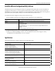
Installation Instructions XM-160, XM-161, and XM-162 Direct Vibration Modules Catalog Numbers 1440-VDRS06-00RH, 1440-VDRS06-06RH, 1440-VDRP06-00RH 1440-VDRx060xRH Topic Page Environment and Enclosure 3 European Hazardous Location Approval 4 North American Hazardous Location Approval 5 Mount the Module 6 Module Indicators 7 Self-Test 8 Reset Switch 8 Install the XM Serial Configuration Utility Software 9 Specifications 9 Additional Resources 11
XM-160, XM-161, and XM-162 Direct Vibration Modules Important User Information Read this document and the documents listed in the additional resources section about installation, configuration, and operation of this equipment before you install, configure, operate, or maintain this product. Users are required to familiarize themselves with installation and wiring instructions in addition to requirements of all applicable codes, laws, and standards.
XM-160, XM-161, and XM-162 Direct Vibration Modules Environment and Enclosure ATTENTION: This equipment is intended for use in a Pollution Degree 2 industrial environment, in overvoltage Category II applications (as defined in IEC 60664-1), at altitudes up to 2000 m (6562 ft) without derating. This equipment is not intended for use in residential environments and may not provide adequate protection to radio communication services in such environments. This equipment is supplied as open-type equipment.
XM-160, XM-161, and XM-162 Direct Vibration Modules ATTENTION: The serial communication port is intended for temporary local-programming purposes only and not intended for permanent connection. The serial cable connections are not to exceed 3.0 m (9.84 ft): • This product is intended to be mounted to a well-grounded mounting surface such as a metal panel or DIN rail. For DIN rail mounting, use zinc plated yellow-chromate steel DIN rail to assure proper grounding.
XM-160, XM-161, and XM-162 Direct Vibration Modules North American Hazardous Location Approval The following information applies when operating this equipment in hazardous locations. Informations sur l'utilisation de cet équipement en environnements dangereux. Products marked "CL I, DIV 2, GP A, B, C, D" are suitable for use in Class I Division 2 Groups A, B, C, D, Hazardous Locations and nonhazardous locations only.
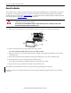
XM-160, XM-161, and XM-162 Direct Vibration Modules Mount the Module The module mounts on a XM® 947 terminal base unit, catalog number 1440-TB-H. We recommend that you mount the modules after connecting the wiring on the terminal base unit. Refer to the XM-947 Direct Vibration Terminal Base Installation Instructions, publication GMSI10-IN027, or the XM-160, XM-161, and XM-162 Direct Vibration Module User Guide, publication GMSI10-UM025, for wiring information.
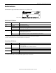
XM-160, XM-161, and XM-162 Direct Vibration Modules Module Indicators Each module has eight status indicators, which are on top of the module. 1440-VDRx06-0xRH Module Indicators Module Status (MS) Indicator Color State Description No color Off No power applied to the module. Green Flashing Red Module performing power-up self-test. Flashing Module operating in Program mode.(1) Solid Module operating in Run mode.(2) Flashing • Application firmware is invalid or not loaded.
XM-160, XM-161, and XM-162 Direct Vibration Modules Channel Status Indicator (six in all) Color State Description No color Off • Normal operation with alarm limits on the channel. • No power applied to the module; look at Module Status indicator. Yellow Solid An alert level alarm condition exists on the channel (and no transducer fault or danger level alarm condition exists). Red Solid A danger level alarm condition exists on the channel (and no transducer fault condition exists).
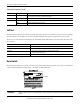
XM-160, XM-161, and XM-162 Direct Vibration Modules Install the XM Serial Configuration Utility Software The XM Documentation and Configuration Utility CD is packaged with the XM modules. It contains the XM Serial Configuration Utility software, a set of user guides, hazardous location installation drawings, and electronic data sheet (EDS) files that are used by network configuration tools such as RSNetWorx™ for DeviceNet software.
XM-160, XM-161, and XM-162 Direct Vibration Modules Attribute XM-16X Emissions CISPR 11 (IEC 61000-6-4) Class A ESD immunity IEC 61000-4-2 8 kV air discharges Radiated RF immunity IEC 61000-4-3 10V/m with 1 kHz sine-wave 80% AM from 80…2000 MHz 10V/m with 200 Hz 50% Pulse 100% AM at 900 MHz 10V/m with 200 Hz 50% Pulse 100% AM at 1890 MHz 3V/m with 1 kHz sine-wave 80% AM from 2000…2700 MHz EFT/B immunity IEC 61000-4-4 ±2 kV at 5 kHz on shielded power ports ±2 kV at 5 kHz on shielded signal ports ±2
XM-160, XM-161, and XM-162 Direct Vibration Modules Certifications Certification(1) (when product is marked) Description c-CSA-us CSA Certified Process Control Equipment for Class I, Division 2 Group A,B,C,D Hazardous Locations, certified for US and Canada. See CSA File 150115. CE European Union 2004/108/EC EMC Directive, compliant with: • EN 61326-1; Meas./Control/Lab.
Rockwell Automation Support Rockwell Automation provides technical information on the Web to assist you in using its products. At http://www.rockwellautomation.com/support you can find technical and application notes, sample code, and links to software service packs. You can also visit our Support Center at https://rockwellautomation.custhelp.com/ for software updates, support chats and forums, technical information, FAQs, and to sign up for product notification updates.