
Manual

Publication GMSI10-UM025C-EN-P - August 2010
Installing the XM-160/161/162 Direct Vibration Module 55
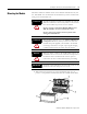
1 Program Mode - Typically this occurs when the module configuration settings are being updated with the XM
Serial Configuration Utility. In Program Mode, the module does not perform its usual functions. The signal
processing/measurement process is stopped, and the status of the alarms is set to the disarm state to prevent
a false alert or danger status.
2 Run Mode - In Run Mode, the module collects measurement data and monitors each measurement device.
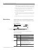
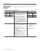
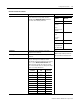
Network Status (NS) Indicator
1 Normal condition when the module is not a slave to an XM-440, PLC, or other master device.
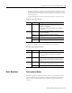
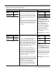
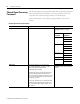
Channel Status Indicator (6 in all)
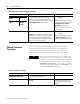
Basic Operations
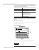
Powering Up the Module
The Direct Vibration modules perform a self-test at power-up. The self-test
includes an LED test and a device test. During the LED test, the indicators
will be turned on independently and in sequence for approximately 0.25
seconds.
Color State Description
No color Off Module is not online.
• Module is autobauding.
• No power is applied to the module, look at Module
Status LED.
Green Flashing Module is online (DeviceNet) but no connections are
currently established.
1
Solid Module is online with connections currently
established.
Red Flashing One or more I/O connections are in the timed-out state.
Solid Failed communications (duplicate MAC ID or bus-off).
Color State Description
No Color Off • Normal operation within alarm limits on the channel.
• No power applied to the module, look at Module
Status LED.
Yellow Solid An alert level alarm condition exists on the channel
(and no transducer fault or danger level alarm condition
exists).
Red Solid A danger level alarm condition exists on the channel
(and no transducer fault condition exists).
Flashing A transducer fault condition exists on the channel.