XM-160/161/162 Direct Vibration Module User Guide Firmware Revision 5 1440-VDRS06-00RH, 1440-VDRS06-06RH, 1440-VDRP06-00RH
Important User Information Solid state equipment has operational characteristics differing from those of electromechanical equipment. Safety Guidelines for the Application, Installation and Maintenance of Solid State Controls (publication SGI-1.1 available from your local Rockwell Automation sales office or online at http://literature.rockwellautomation.com) describes some important differences between solid state equipment and hardwired electromechanical devices.
Safety Approvals The following information applies when operating this equipment in hazardous locations. Informations sur l’utilisation de cet équipement en environnements dangereux. Products marked "CL I, DIV 2, GP A, B, C, D" are suitable for use in Class I Division 2 Groups A, B, C, D, Hazardous Locations and nonhazardous locations only. Each product is supplied with markings on the rating nameplate indicating the hazardous location temperature code.
Table of Contents Chapter 1 Introduction Introducing the XM-160, XM-161, and XM-162 Modules . . . . . . . . . . 1 XM-160, XM-161, and XM-162 Module Components . . . . . . . . . . . . . 2 Using this Manual. . . . . . . . . . . . . . . . . . . . . . . . . . . . . . . . . . . . . . . . . . . 3 Organization. . . . . . . . . . . . . . . . . . . . . . . . . . . . . . . . . . . . . . . . . . . . 3 Document Conventions . . . . . . . . . . . . . . . . . . . . . . . . . . . . . . . . . .
Table of Contents vi Data Parameters . . . . . . . . . . . . . . . . . . . . . . . . . . . . . . . . . . . . . . . . . . . 74 Channel Data Parameters . . . . . . . . . . . . . . . . . . . . . . . . . . . . . . . . 74 Alarm and Relay Status Parameters . . . . . . . . . . . . . . . . . . . . . . . . 75 Device Mode Parameters . . . . . . . . . . . . . . . . . . . . . . . . . . . . . . . . . . . . 76 Appendix A Specifications . . . . . . . . . . . . . . . . . . . . . . . . . . . . . . . . . . . . . . . . .
Table of Contents vii Parameter Object (Class ID 0FH). . . . . . . . . . . . . . . . . . . . . . . . . . . . 104 Class Attributes . . . . . . . . . . . . . . . . . . . . . . . . . . . . . . . . . . . . . . . 104 Instances. . . . . . . . . . . . . . . . . . . . . . . . . . . . . . . . . . . . . . . . . . . . . 105 Instance Attributes. . . . . . . . . . . . . . . . . . . . . . . . . . . . . . . . . . . . . 109 Services . . . . . . . . . . . . . . . . . . . . . . . . . . . . . . . . . . . . . . . . . . . . .
Table of Contents viii Publication GMSI10-UM025C-EN-P - August 2010
Chapter 1 Introduction This chapter provides an overview of the XM-160 Direct Vibration module, the XM-161 Direct Vibration with 4-20mA module, and the XM-162 Direct Vibration with Power module. It also discusses the components of the modules.
2 Introduction The modules also include a buffer output for each input signal; can connect up to two XM-441 Expansion Relay modules, providing a total of eight relays, and collect trend data based on an event such as a relay actuation.
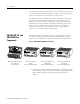
Introduction 3 • XM-160/161/162 Direct Vibration Module - The module mounts on the XM-947 terminal base via a keyswitch and a 96-pin connector. The module contains the measurement electronics, processors, and serial interface port for local configuration. IMPORTANT Up to two XM-441 Expansion Relay modules may be connected to the XM-160, XM-161, or XM-162 module via the XM-947 terminal base.
4 Introduction For definitions of terms used in this Guide, see the Glossary at the end of the Guide. Document Conventions There are several document conventions used in this manual, including the following: The XM-160, XM-161, and XM-162 Direct Vibration modules are referred to as XM-160/161/162, Direct Vibration modules, devices, or modules throughout this manual. Direct vibration is a common term for an unfiltered overall vibration measurement and can be used interchangeably with “Overall.
Chapter 2 Installing the XM-160/161/162 Direct Vibration Module This chapter discusses how to install and wire the XM-160, XM-161, and XM-162 Direct Vibration modules. It also describes the module indicators and the basic operations of the modules.
6 Installing the XM-160/161/162 Direct Vibration Module XM Installation Requirements This section describes wire, power, and grounding requirements for an XM system Wiring Requirements Use solid or stranded wire. All wiring should meet the following specifications: • 14 to 22 AWG copper conductors without pretreatment; 8 AWG required for grounding the DIN rail for electromagnetic interference (emi) purposes • Recommended strip length 8 millimeters (0.
Installing the XM-160/161/162 Direct Vibration Module 7 Figure 2.
8 Installing the XM-160/161/162 Direct Vibration Module IMPORTANT See Application Technique "XM Power Supply Solutions", publication ICM-AP005A-EN-E, for guidance in architecting power supplies for XM systems. Grounding Requirements Use these grounding requirements to ensure safe electrical operating circumstances, and to help avoid potential emi and ground noise that can cause unfavorable operating conditions for your XM system.
Installing the XM-160/161/162 Direct Vibration Module 9 Figure 2.
10 Installing the XM-160/161/162 Direct Vibration Module Figure 2.3 DIN Rail Grounding Block Panel/Wall Mount Grounding The XM modules can also be mounted to a conductive mounting plate that is grounded. See Figure 2.5. Use the grounding screw hole provided on the terminal base to connect the mounting plate the Chassis terminals. Figure 2.
Installing the XM-160/161/162 Direct Vibration Module 11 Figure 2.5 Panel/Wall Mount Grounding 1 Power Supply 1 Power Supply 1 Use 14 AWG wire.
12 Installing the XM-160/161/162 Direct Vibration Module 24V Common Grounding 24V power to the XM modules must be grounded. When two or more power supplies power the XM system, ground the 24V Commons at a single point, such as the ground bus bar. IMPORTANT IMPORTANT If it is not possible or practical to ground the -24Vdc supply, then it is possible for the system to be installed and operate ungrounded.
Installing the XM-160/161/162 Direct Vibration Module 13 Figure 2.6 Grounded DeviceNet V- at XM Module To Ground Bus ATTENTION Use of a separate DeviceNet power supply is not permitted. See Application Technique "XM Power Supply Solutions", publication ICM-AP005A-EN-E, for guidance in using XM with other DeviceNet products. For more information on the DeviceNet installation, refer to the ODVA Planning and Installation Manual - DeviceNet Cable System, which is available on the ODVA web site (http://www.
14 Installing the XM-160/161/162 Direct Vibration Module DIN Rail Mounting Use the following steps to mount the XM-947 terminal base unit on a DIN rail (A-B pt no. 199-DR1 or 199-DR4). 1. Position the terminal base on the 35 x 7.5mm DIN rail (A). Position terminal base at a slight angle and hook over the top of the DIN rail. 2. Slide the terminal base unit over leaving room for the side connector (B). 3.
Installing the XM-160/161/162 Direct Vibration Module 15 4. Press down on the terminal base unit to lock the terminal base on the DIN rail. If the terminal base does not lock into place, use a screwdriver or similar device to open the locking tab, press down on the terminal base until flush with the DIN rail and release the locking tab to lock the base in place. Interconnecting Terminal Base Units Follow the steps below to install another terminal base unit on the DIN Rail.
16 Installing the XM-160/161/162 Direct Vibration Module Panel/Wall Mounting Installation on a wall or panel consists of: • laying out the drilling points on the wall or panel • drilling the pilot holes for the mounting screws • installing the terminal base units and securing them to the wall or panel Use the following steps to install the terminal base on a wall or panel. 1. Lay out the required points on the wall/panel as shown in the drilling dimension drawing below. Side Connector 2.
Installing the XM-160/161/162 Direct Vibration Module Connecting Wiring for Your Module 17 Wiring to the module is made through the terminal base unit on which the module mounts. The XM-160, XM-161, and XM-162 modules are compatible only with the XM-947 terminal base unit, Cat. No. 1440-TB-H. Figure 2.7 XM-947 Terminal Base Unit XM-947, Cat. No. 1440-TB-H Terminal Block Assignments The terminal block assignments and descriptions for the XM-160, XM-161, and XM-162 modules are shown below.
18 Installing the XM-160/161/162 Direct Vibration Module Terminal Block Assignments Name No.
Installing the XM-160/161/162 Direct Vibration Module 19 Terminal Block Assignments Name No. XM-160 XM-161 XM-162 Description 34 No Connection 4-20mA 1...3 V+ GND/COM XM-161 channel 1, 2, & 3 4-20mA positive voltage supply input (4-20mA loops returned directly to external power source) XM-162 circuit ground (Relay Reset and SetPtMult switch return) 35 No Connection 4-20mA 1...
20 Installing the XM-160/161/162 Direct Vibration Module Connecting the Power Supply Power supplied to the module must be nominally 18–32 Vdc and must be a Class 2 rated circuit. Wire the DC-input power supply to the terminal base unit as shown in Figure 2.8.
Installing the XM-160/161/162 Direct Vibration Module ATTENTION 21 The power connections are different for different XM modules. Refer to the installation instructions for your specific XM module for complete wiring information. Connecting the Buffered Outputs The XM-160, XM-161, and XM-162 provide buffered outputs of all transducer input signals (a total of six). The buffered output connections may be used to connect the module to portable data collectors.
22 Installing the XM-160/161/162 Direct Vibration Module The XM-161 requires an external DC power supply to provide loop power. The DC power supply must meet the following requirements: • Minimum: 7V dc • Maximum: 36V dc To determine the minimum voltage across the total loop, add the resistance of all loads in the loop, and determine the minimum operating voltage using the following formula: Voltage minimum = 7 + ( .
Installing the XM-160/161/162 Direct Vibration Module 23 Figure 2.10 Loop-powered 4-20mA Connections Channel 1 4-20mA Out + Channel 2 4-20mA Out + Channel 3 4-20mA Out + 4-20mA V+ (Channel 1 to 3) Loop Power Supply 7 - 36V * 34 16 17 18 + - Channel 4 4-20mA Out + Digital Meter Channel 5 4-20mA Out + PLC Load 250 ohm Typical 50 Recorder 31 32 33 Channel 6 4-20mA Out + PLC 4-20mA V+ (Channel 4 to 6) Recorder Digital Meter *Note: Single power supply will not provide isolated banks of three.
24 Installing the XM-160/161/162 Direct Vibration Module The XM-161 and XM-162 modules can be wired to a Remote Relay Reset Signal. To activate the switch, the switch input terminal should be connected to ground/common. The XM-162 module provides a dedicated terminal for this purpose. However, the XM-161 module does not. Therefore, the input terminal must be wired to any of the XM-161 module’s Signal Common or 24V Power Supply GND/COM terminals.
Installing the XM-160/161/162 Direct Vibration Module 25 Figure 2.12 Typical Multiple XM Modules Remote Relay Reset Signal Connection Connecting the Setpoint Multiplication Switch (XM-161 & XM-162) You can configure the Direct Vibration modules to multiply the alarm setpoints, or inhibit the alarms during the start-up period. This can be used to avoid alarm conditions that may occur during startup, for example, when the monitored machine passes through a critical speed.
26 Installing the XM-160/161/162 Direct Vibration Module Figure 2.13 Setpoint Multiplication Connections Connecting the Transducers The Direct Vibration Modules can accept input from any Allen-Bradley non-contact eddy current probe, a standard IEPE accelerometer, a velocity transducer, or AC voltage output measurement device. Connecting an IEPE Accelerometer The following figures show the wiring of an IEPE accelerometer to the terminal base unit.
Installing the XM-160/161/162 Direct Vibration Module 27 Figure 2.14 IEPE Accelerometer to Channel 1 Wiring TYPICAL WIRING FOR IEPE ACCELEROMETER TO XM-160/161/162 DIRECT VIBRATION MODULE CHANNEL 1 Pin A - Signal Pin B - Common Cable shield not connected at this end Channel 1 Input Signal Shield 0 Channel 1 Input Signal Signal Common 19 3 Figure 2.
28 Installing the XM-160/161/162 Direct Vibration Module Figure 2.16 IEPE Accelerometer to Channel 3 Wiring TYPICAL WIRING FOR IEPE ACCELEROMETER TO XM-160/161/162 DIRECT VIBRATION MODULE CHANNEL 3 Pin A - Signal Pin B - Common Cable shield not connected at this end Channel 1 Input Signal Shield 2 Channel 3 Input Signal 23 Signal Common 7 Figure 2.
Installing the XM-160/161/162 Direct Vibration Module 29 Figure 2.18 IEPE Accelerometer to Channel 5 Wiring TYPICAL WIRING FOR IEPE ACCELEROMETER TO XM-160/161/162 DIRECT VIBRATION MODULE CHANNEL 5 Pin A - Signal Pin B - Common Cable shield not connected at this end Shield 42 Channel 5 Input Signal Signal Common 27 11 Figure 2.
30 Installing the XM-160/161/162 Direct Vibration Module Connecting a Non-Contact Sensor to the XM-162 The figures below show the wiring of a non-contact sensor to the terminal base unit of the XM-162 module. The XM-162 module provides an internal DC power supply for powering a standard -24V non-contact eddy current probe driver. Refer to Connecting a Non-Contact Sensor to the XM-160 and 161 on page 33 to see how to wire the XM-160 and XM-161 modules to a non-contact sensor.
Installing the XM-160/161/162 Direct Vibration Module 31 Figure 2.21 Non-Contact Sensor to XM-162 Channel 2 Wiring T Y P IC A L W IR IN G F O R N O N - C O N T A C T S E N S O R T O X M -1 6 2 D I R E C T V IB R A T I O N M O D U L E C H A N N E L 2 Isolated Sensor Driver -24 SIG COM Shield F l o a t in g -24V DC Shield 17 Channel 2 Input Signal Signal Common 1 21 5 Figure 2.
32 Installing the XM-160/161/162 Direct Vibration Module Figure 2.23 Non-Contact Sensor to XM-162 Channel 4 Wiring T Y P IC A L W IR IN G F O R N O N - C O N T A C T S E N S O R T O X M - 1 6 2 D I R E C T V IB R A T I O N M O D U L E C H A N N E L 4 Isolated Sensor Driver -24 SIG COM S h ie ld Floating Shield Channel 4 Input Signal Signal Common 41 25 -24V DC 9 31 Figure 2.
Installing the XM-160/161/162 Direct Vibration Module 33 Figure 2.
34 Installing the XM-160/161/162 Direct Vibration Module Figure 2.
Installing the XM-160/161/162 Direct Vibration Module 35 Figure 2.
36 Installing the XM-160/161/162 Direct Vibration Module Figure 2.
Installing the XM-160/161/162 Direct Vibration Module 37 Figure 2.
38 Installing the XM-160/161/162 Direct Vibration Module Figure 2.
Installing the XM-160/161/162 Direct Vibration Module 39 Figure 2.31 Non-Contact Sensor to XM-160/161 Channel 6 Wiring TYPICAL WIRING FOR NON-CONTACT SENSOR TO XM-160/161 DIRECT VIBRATION MODULE CHANNEL 6 Isolated Sensor Driver -24 SIG COM Shield Floating Channel 6 Input Signal Signal Common Shield 29 15 + -24V DC 13 - +24V DC Isolated Power Supply Connecting a Passive Transducer The figures below show the wiring of a passive transducer, such as a velocity sensor, to the terminal base unit.
40 Installing the XM-160/161/162 Direct Vibration Module Figure 2.32 Velocity Sensor to Channel 1 Wiring TYPICAL WIRING FOR COIL-BASED VELOCITY SENSOR TO XM-160/161/162 DIRECT VIBRATION MODULE CHANNEL 1 Pin A - Signal Pin B - Common Cable shield not connected at this end Channel 1 Input Signal Shield 0 Channel 1 Input Signal Signal Common 19 3 Figure 2.
Installing the XM-160/161/162 Direct Vibration Module 41 Figure 2.34 Velocity Sensor to Channel 3 Wiring TYPICAL WIRING FOR COIL-BASED VELOCITY SENSOR TO XM-160/161/162 DIRECT VIBRATION MODULE CHANNEL 3 Pin A - Signal Pin B - Common Cable shield not connected at this end Channel 1 Input Signal Shield 2 Channel 3 Input Signal 23 Signal Common 7 Figure 2.
42 Installing the XM-160/161/162 Direct Vibration Module Figure 2.36 Velocity Sensor to Channel 5 Wiring TYPICAL WIRING FOR COIL-BASED VELOCITY SENSOR TO XM-160/161/162 DIRECT VIBRATION MODULE CHANNEL 5 Pin A - Signal Pin B - Common Cable shield not connected at this end Shield 42 Channel 5 Input Signal Signal Common 27 11 Figure 2.
Installing the XM-160/161/162 Direct Vibration Module 43 Connecting a Powered Sensor The figures below show the wiring of a powered sensor, such as the Model 580 Vibration Pickup, to the terminal base unit. ATTENTION You may ground the cable shield at either end of the cable. Do not ground the shield at both ends. Recommended practice is to ground the cable shield at the terminal base and not at the transducer. Any convenient Chassis terminal may be used (see Terminal Block Assignments on page 17).
44 Installing the XM-160/161/162 Direct Vibration Module Figure 2.
Installing the XM-160/161/162 Direct Vibration Module 45 Figure 2.
46 Installing the XM-160/161/162 Direct Vibration Module Figure 2.
Installing the XM-160/161/162 Direct Vibration Module 47 Figure 2.
48 Installing the XM-160/161/162 Direct Vibration Module Figure 2.
Installing the XM-160/161/162 Direct Vibration Module 49 Connecting an IEPE Accelerometer and Non-Contact Sensor Figure 2.44 shows the wiring of an IEPE accelerometer and a non-contact sensor to the XM-162 terminal base unit. IMPORTANT The IEPE Power in the XM-160/161/162 module is configurable in channel pairs: Channels 1 and 2, Channels 3 and 4, and Channels 5 and 6.
50 Installing the XM-160/161/162 Direct Vibration Module Figure 2.
Installing the XM-160/161/162 Direct Vibration Module 51 A special cable (Cat. No. 1440-SCDB9FXM2) is required for this serial connection. The connector that inserts into the PC is a DB-9 female connector, and the connector that inserts into the module is a USB Mini-B male connector. WARNING IMPORTANT If you connect or disconnect the serial cable with power applied to the module or the serial device on the other end of the cable, an electrical arc can occur.
52 Installing the XM-160/161/162 Direct Vibration Module IMPORTANT The DeviceNet power circuit through the XM module interconnect, which is rated at only 300 mA, is not intended or designed to power DeviceNet loads. Doing so could damage the module or terminal base. To preclude this possibility, even unintentionally, it is recommended that DeviceNet V+ be left unconnected. ATTENTION ATTENTION ATTENTION IMPORTANT You must ground the DeviceNet shield at only one location.
Installing the XM-160/161/162 Direct Vibration Module Mounting the Module 53 The Direct Vibration modules mount on the XM-947 terminal base unit, Cat. No. 1440-TB-H. You should mount the module after you have connected the wiring on the terminal base unit. ATTENTION The Direct Vibration modules are compatible only with the XM-947 terminal base unit. The keyswitch on the terminal base unit should be at position 7 for the modules.
54 Installing the XM-160/161/162 Direct Vibration Module 2. Make certain the side connector (B) is pushed all the way to the left. You cannot install the module unless the connector is fully extended. 3. Make sure that the pins on the bottom of the module are straight so they will align properly with the connector in the terminal base unit. 4. Position the module (D) with its alignment bar (E) aligned with the groove (F) on the terminal base. 5.
Installing the XM-160/161/162 Direct Vibration Module 55 1 Program Mode - Typically this occurs when the module configuration settings are being updated with the XM Serial Configuration Utility. In Program Mode, the module does not perform its usual functions. The signal processing/measurement process is stopped, and the status of the alarms is set to the disarm state to prevent a false alert or danger status.
56 Installing the XM-160/161/162 Direct Vibration Module The device test occurs after the LED test. The Module Status (MS) indicator is used to indicate the status of the device self-test. MS Indicator State Description Flashing Red and Green Device self test is in progress. Solid Green or Flashing Green Device self test completed successfully, and the firmware is valid and running. Flashing Red • Device self test completed, the hardware is OK, but the firmware is invalid.
Chapter 3 Configuration Parameters This chapter provides a complete listing and description of the XM-160, XM161, and XM-162 parameters. The parameters can be viewed and edited using the XM Serial Configuration Utility software and a personal computer. If the module is installed on a DeviceNet network, configuring can also be performed using a network configuration tool such as RSNetWorx (Version 3.0 or later). Refer to your configuration tool documentation for instructions on configuring a device.
58 Configuration Parameters IEPE Buffer Power and Signal Detection Parameters Use these parameters to configure the IEPE and buffer power options and to determine the measurement performed on the input signal to produce the overall value. IEPE Buffer Power and Signal Detection Parameters Parameter Name Description XM Configuration EDS File Utility Controls whether to provide standard accelerometer (IEPE) power to the transducer.
Configuration Parameters 59 IEPE Buffer Power and Signal Detection Parameters Parameter Name Description XM Configuration EDS File Utility Enable IEPE Voltage Boost IEPE Voltage Boost Values/Comments Boosts the supply voltage to IEPE power when the module power supply voltage drops below 22V dc. This parameter is intended for battery-powered applications that experience low voltage situations (down to 18V dc) with slow battery drain, and high voltage situations (up to 32V dc) as the battery charges.
60 Configuration Parameters IEPE Buffer Power and Signal Detection Parameters Parameter Name XM Configuration EDS File Utility Buffer Power Type Buff Pwr Manual Setting Description Values/Comments Manual setting of the buffer power circuits. Determines whether the buffered output circuits swing the positive range (nominally +0.6V dc to +22.5V dc) or the negative range (-22V dc to +3V dc). See Auto Buffer Power for more details.
Configuration Parameters 61 Channel Transducer Parameters Parameter Name Description Values/Comments Eng. Units Defines the native units of the transducer. Your choice controls the list of possible selections available in the Output Data Units parameter. It also affects other module parameters. Eng.
62 Configuration Parameters Channel Signal Processing Parameters The channel signal processing parameters determine the signal processing that will be performed on the input signals. Use these parameters to select the output data units, full scale settings, and the low cutoff frequency. There are six instances of the signal processing parameters, one for each channel.
Configuration Parameters 63 Channel Signal Processing Parameters Parameter Name Description Values/Comments High Pass Filter Sets the high pass filter to apply to the measurements. The high pass filter is useful in removing low frequency signal components that would dominate the signal. The high pass filter attenuates all frequencies below a defined frequency. It allows, or passes, frequencies above the defined frequency.
64 Configuration Parameters Alarm Parameters The Alarm parameters control the operation of the alarms (alert and danger level) and provide alarm status. The XM-160, XM-161, and XM-162 modules provide six alarms. The alarms are associated with the direct (overall) value measured from the respective channel (1 to 6). Use the parameters to configure the behavior of the alarm.
Configuration Parameters 65 Alarm Parameters Parameter Name Description Values/Comments Alert Threshold (High) The threshold value for the alert (alarm) condition. Same measurement unit as Output Data Unit selection for the specified channel. Note: This parameter is the greater threshold value when Condition is set to "Inside Range" or "Outside Range." Danger Threshold (High) The threshold value for the danger (shutdown) condition.
66 Configuration Parameters Alarm Parameters Parameter Name Description Values/Comments Startup Period The length of time that the Threshold Multiplier is applied to the threshold. The startup period begins when the setpoint multiplier switch is reopened (push button disengaged or toggle switch flipped to off). Enter a value from 0 to 1092 minutes, adjustable in increments of 0.1 minutes.
Configuration Parameters 67 Relay Parameters Parameter Name Description Options/Comments Number (XM Serial Configuration Utility only) Sets the relay to be configured in the XM Serial Configuration Utility. The relays are either relays on the Expansion Relay module when it is connected to the XM-160, XM-161, or XM-162 or virtual relays. Virtual relays are non-physical relays.
68 Configuration Parameters Relay Parameters Parameter Name Description XM Configuration EDS File Utility Activation Logic Logic XM Configuration EDS File Utility Alarm A/B Alarm Identifier A/B XM Configuration EDS File Utility Alarm Status to Activate On Options: A only A or B A and B • A or B - Relay is activated when either Alarm A or Alarm B meets or exceeds the selected Alarm Status condition(s).
Configuration Parameters 69 Relay Parameters Parameter Name Description XM Configuration EDS File Utility Failsafe Relay Failsafe Option Options/Comments Determines whether the relay is failsafe or non-failsafe. Failsafe operation means that when in alarm, the relay contacts are in their "normal," de-energized, or "shelf-state" positions. In other words, normally closed relays are closed in alarm, and normally open relays are open in alarm. With failsafe operation, a power failure equals an alarm.
70 Configuration Parameters 4-20mA Output Parameters (XM-161) The 4-20mA output parameters define the characteristics of the 4-20mA output signals. The XM-161 supports a total of six 4-20mA outputs. Each output is permanently associated with a corresponding channel. The parameters are the same for each output. IMPORTANT The 4-20mA output parameters are available only in the XM-161 module.
Configuration Parameters Triggered Trend 71 The XM-160/161/162 modules can collect a triggered trend. A triggered trend is a time-based trend that is collected when a relay is activated, or the module receives a trigger event. Once the triggered trend is configured, the XM module continuously monitors the trended measurements. When a trigger occurs, the XM module collects additional data as specified by the Post Trigger parameter. The XM-160/161/162 can only store one triggered trend.
72 Configuration Parameters Triggered Trend Parameters Parameter Name Description Values/Comments Relay Number Sets the relay that triggers the trend to be collected. None means that the trend can only be triggered manually or by a trigger event (for example, XM-440). Relay Numbers 1 through 8 are either relays on the Expansion Relay module when it’s connected to the module or virtual relays. Note: The relay must be enabled. Refer to Relay Parameters on page 66.
Configuration Parameters I/O Data Parameters 73 The I/O data parameters are used to configure the content and size of the DeviceNet I/O Poll response message. IMPORTANT The XM-160/161/162 modules must be free of Poll connections when configuring the Poll Output (Poll Response Assembly) and Poll Size. Any attempt to download the parameters while a master device has established the Poll connection with the XM module will result in an error.
74 Configuration Parameters The Data parameters are used to view the measured values of the input channels and to monitor the status of the channels, alarms, and relays. Data Parameters TIP To view all the data parameters in the XM Serial Configuration Utility, click the View Data tab. Channel Data Parameters Channel Data Parameters Parameter Name Description Values/Comments Status States whether a fault exists on the associated channel. If a fault exists, the overall value may not be accurate.
Configuration Parameters 75 Alarm and Relay Status Parameters Alarm and Relay Status Parameters Parameter Name Description Values/Comments Alarm Status States the current status of the alarm. Possible status values: • Normal - The alarm is enabled, the device is in Run mode, there is no transducer fault, and the current measurement is not within the Alert or Danger Threshold value(s).
76 Configuration Parameters Device Mode Parameters The Device Mode parameters are used to control the functions and the behavior of the device. IMPORTANT The XM Serial Configuration Utility handles these parameters automatically and transparently to the user. Device Mode Parameters Parameter Name Description Values/Comments Device Mode Sets the current operation mode of the device. Refer to Changing Operation Modes on page 83 for more information.
Appendix A Specifications Appendix A lists the technical specifications for the XM-160/161/162 Direct Vibration modules. XM-160/161/162 Direct Vibration Technical Specifications Product Feature Specification Communications DeviceNet Standard DeviceNet protocol for all functions NOTE: The XM-160/161/162 uses only the DeviceNet protocol, not power. Module power is provided independently.
78 Specifications XM-160/161/162 Direct Vibration Technical Specifications Product Feature Specification Inputs 6 Channels Eddy current transducer signals IEPE Accelerometer signals Voltage signals from any dynamic measurement device, such as a velocity or pressure transducer Transducer Power IEPE constant current (2.69mA ±20% from +24V dc) None (voltage input) Constant voltage (-24V dc) (XM-162 only): max 20mA per channel Voltage Range ±24V dc 6.
Specifications 79 XM-160/161/162 Direct Vibration Technical Specifications Product Feature Specification Indicators 8 LEDs Module Status - red/green Network Status - red/green Channel 1 Status - yellow/red Channel 2 Status - yellow/red Channel 3 Status - yellow/red Channel 4 Status - yellow/red Channel 5 Status - yellow/red Channel 6 Status - yellow/red Vibration Measurement & Signal Conditioning A/D Conversion 12 bits Resolution 0.
80 Specifications XM-160/161/162 Direct Vibration Technical Specifications Product Feature Specification Trend Buffer Number or Records 1 to 12 parameters Time Interval 1 to 3600 seconds Trigger Relay on the XM-441 Expansion Relay module is activated, or by a trigger event (for example, DeviceNet command from a controller or host). The data collected in the buffer is user configurable in software.
Specifications 81 XM-160/161/162 Direct Vibration Technical Specifications Product Feature Specification Relays Number Up to eight relays when interconnected to one or two XM-441 Expansion Relay modules, or Eight virtual relays whose status can be used by remote control systems Failsafe Normally energized (failsafe), or Normally de-energized (non-fail-safe) Latching Latching, or Non-latching Time Delay 0 to 25.
82 Specifications XM-160/161/162 Direct Vibration Technical Specifications Product Feature Specification Environmental Operating Temperature -20 to +65°C (-4 to +149°F) Storage Temperature -40 to +85°C (-40 to +185°F) Relative Humidity 95% non-condensing Physical Dimensions Height: 3.8in (97mm) Width: 3.7in (94mm) Depth: 3.7in (94mm) Terminal Screw Torque 7 pound-inches (0.
Appendix B DeviceNet Information Electronic Data Sheets Electronic Data Sheet (EDS) files are simple text files used by network configuration tools such as RSNetWorx (Version 3.0 or later) to help you identify products and easily commission them on a network. The EDS files describe a product’s device type, product revision, and configurable parameters on a DeviceNet network. The EDS files for the XM modules are installed on your computer with the XM configuration software.
84 DeviceNet Information Transition to Program Mode Parameter values can only be downloaded to an XM module while the module is in Program mode. Any attempt to download a parameter value while the module is in Run mode will result in a Device State Conflict error. To transition an XM module from Run mode to Program mode on a DeviceNet network, set the Device Mode parameter to "Program mode" and click Apply.
DeviceNet Information 85 The table below defines services supported by XM modules. The table includes the service codes, class instances, and attributes by their appropriate hexadecimal codes. Use the Class Instance Editor in RSNetWorx to execute these services, all illustrated in the example below.
86 DeviceNet Information Example To save the configuration parameters to the non-volatile memory (EEPROM), fill in the Class Instance Editor as shown below. Clear Send the attribute ID and then enter the Class (320 hex) and Instance (1) Select the Save service code Click Execute to initiate the action Invalid Configuration Errors A Start or Save service request to an XM module may return an Invalid Device Configuration error when there is a conflict amongst the configuration settings.
DeviceNet Information 87 Additional Error Codes returned with the Invalid Device Configuration Error (0xD0) XM-160/161/162 I/O Message Formats Error Code (Hex) Description 0B Invalid node address in the alarm list. 0C Too many alarms in the alarm list. Or, no alarms in the alarm list. 0D Alarm levels cannot be zero for alarms that are enabled. 0E Too many slaves in the scanner’s input data table. 0F The FMAX and Number of Lines do not yield correct vector calculations.
88 DeviceNet Information The Poll response data can also be requested explicitly through Assembly Object (Class ID 0x4), Instance 101 (0x65), Data Attribute (3). The following table shows the static data format of Assembly instance 101.
DeviceNet Information 89 XM-160/161/162 COS Message Format Byte Bit 7 Bit 6 Bit 5 Bit 4 Bit 3 Bit 2 Bit 1 5 Relay 6 Status Reserved Reserved Reserved 6 Relay 7 Status Reserved Reserved Reserved 7 Relay 8 Status Reserved Reserved Reserved Bit 0 XM Status Values The following tables describe the XM Status values that are included in the COS messages.
90 DeviceNet Information Figure B.1 Bit-Strobe Command The XM modules use the bit received in a Bit-Strobe connection as a trigger event. When the bit number corresponding to the XM module’s node address is set, the XM module will collect the triggered trend data. Note that the XM modules do not send data in the Bit-Strobe response. ADR for XM Modules Automatic Device Replacement (ADR) is a feature of an Allen-Bradley DeviceNet scanner.
DeviceNet Information 91 • The ADR scanner can not download the configuration data to an XM module if the module has a saved configuration in its non-volatile memory. This happens because the saved configuration is restored and the module enters Run mode when the power is cycled. (Configuration parameters cannot be downloaded while an XM module is in Run mode.) XM modules must be in Program mode for the ADR configuration to be downloaded and this occurs only when there is no saved configuration.
92 DeviceNet Information – All SU/CD Trend related parameters – Custom Assembly structure (see page 73) • The ADR and trigger group functions cannot be used together. A module can have only one primary master so a module cannot be both configured for ADR and included in a trigger group. The ADR scanner must be the primary master for the modules configured for ADR. The XM-440 Master Relay module must be the primary master for modules included in a trigger group.
Appendix C DeviceNet Objects Appendix C provides information on the DeviceNet objects supported by the Direct Vibration modules.
94 DeviceNet Objects The Identity Object provides identification and general information about the device. Identity Object (Class ID 01H) Class Attributes The Identity Object provides no class attributes. Instance Attributes Table C.
DeviceNet Objects 95 Table C.2 Identity Object Status Bit Name 3 Description Reserved, set to 0 4 Boot Program 5-7 Vendor-specific, indicates that the boot program is running. The Main Application must be corrupt or missing. Vendor-specific, not implemented 8 Minor Recoverable Fault Set whenever there is a transducer or tachometer fault.
96 DeviceNet Objects Class Attributes Table C.4 DeviceNet Object Class Attributes Attr ID Access Rule Name Data Type Default Value 1 Get Revision UINT 2 Instance Attributes Table C.
DeviceNet Objects 97 The Assembly Object binds attributes of multiple objects to allow data to or from each object to be sent or received in a single message. Assembly Object (Class ID 04H) The XM-160, XM-161, and XM-162 modules provide both static and dynamic assemblies. Class Attribute Table C.6 Assembly Object Class Attributes Attr ID Access Rule Name Data Type Description Semantics 1 Get Revision UINT Revision of the implemented object. 2 Instances Table C.
98 DeviceNet Objects Table C.8 Assembly Object Instance Attributes Attr ID Access Rule Name Data Type Value 2 Set Member List Array of STRUCT: Only supported for Dynamic Assembly instance Member Data Description 3 Get UINT Size of member data value in bits Member Path Size UINT Member Path Packed EPATH Data Defined in tables on the following pages.
DeviceNet Objects 99 Instance 101 - Measurement Values This is the default assembly that is sent within the I/O Poll Response message when an I/O Poll Request is received from a DeviceNet Master. Table C.
100 DeviceNet Objects Table C.
DeviceNet Objects 101 Services Table C.12 Assembly Object Services Connection Object (Class ID 05H) Service Code Class/Instance Usage Name 0Eh Class/Instance Get_Attribute_Single 10h Instance Set_Attribute_Single 08h Class Create 09h Instance Delete The Connection Object allocates and manages the internal resources associated with both I/O and Explicit Messaging Connections. Class Attributes The Connection Object provides no class attributes. Instances Table C.
102 DeviceNet Objects Instance Attributes Table C.14 Connection Object Instance Attributes Attr ID Access Rule Name Data Type Description 1 Get State USINT State of the object. 2 Get Instance Type USINT Indicates either I/O or Messaging Connection. 3 Get Transport Class Trigger BYTE Defines behavior of the Connection. 4 Get Produced Connection ID UINT Placed in CAN Identifier Field when the Connection transmits.
DeviceNet Objects 103 Services Table C.15 Connection Object Services Discrete Input Point Object (Class ID 08H) Service Code Class/Instance Usage Name 05h Instance Reset 0Eh Instance Get_Attribute_Single 10h Instance Set_Attribute_Single The Discrete Input Point Object stores information about the value of the Setpoint Multiplier signal. Class Attributes Table C.
104 DeviceNet Objects Services Table C.18 Discrete Input Object Services Service Code Class/Instance Usage Name Description 0Eh Class/Instance Get_Attribute_Single Returns the contents of the specified attribute. 10h Instance Set_Attribute_Single Sets the contents of the specified attribute. 32h Instance Open Opens the virtual Setpoint Multiplier switch. 33h Instance Close Closes the virtual Setpoint Multiplier switch.
DeviceNet Objects 105 Instances There are 30 instances of this object. Table C.
106 DeviceNet Objects Table C.
DeviceNet Objects 107 Table C.
108 DeviceNet Objects Table C.
DeviceNet Objects 109 Table C.
110 DeviceNet Objects Table C.21 Parameter Object Instance Attributes Attr ID Access Rule Name Data Type Description Semantics 4 Get Descriptor WORD Description of Parameter Bit 0 = Settable Path support Bit 1 = Enum Strings support Bit 2 = Scaling support Bit 3 = Scaling Links support Bit 4 = Read Only Bit 5 = Monitor Bit 6 = Ext. Prec. scaling 5 Get Data Type EPATH Data Type Code See DeviceNet Specification Volume 1 Appendix J, Section J-6.
DeviceNet Objects 111 Instances A module provides only a single instance (instance 1) of the Acknowledge Handler Object. This instance is associated with instance 4 of the Connection Object, the slave COS connection to a higher level master. Instance Attributes Table C.
112 DeviceNet Objects Instances There are 6 instances of this object. Instance Attributes Table C.26 Alarm Object Instance Attributes Attr ID Access Rule Name Data Type Description Semantics 3 Get Alarm Status 3 BITS The current status of the alarm. 0 = Normal 1 = Alert (alarm) 2 = Danger (shutdown) 3 = Disarm 4 = Xdcr Fault 5 = Module Fault 4 Get/Set Alarm Enable BOOL Indicates whether this alarm object is enabled.
DeviceNet Objects 113 Table C.26 Alarm Object Instance Attributes Attr ID Access Rule 13 Get/Set 14 18 Name Data Type Description Semantics Threshold (Setpoint REAL Multiplier) Indicates how the thresholds should be adjusted when the setpoint multiplication function is invoked. 0 = Disable alarm > 0 = Multiply the thresholds by the value Get/Set Startup Period UINT The amount of time that the Threshold (Setpoint) Multiplier is applied after the startup signal is received.
114 DeviceNet Objects Instance Attributes Table C.28 Channel Object Instance Attributes Attr ID Access Rule 3 Get/Set Name Data Type Description Semantics Output Data Units ENGUNIT The data units of the signal resulting from the signal processing performed in the channel. See DeviceNet Specification Volume 1 Appendix K. Also see Parameter Object Instances 7 to 12.
DeviceNet Objects 115 Services Table C.29 Channel Object Services Service Code Class/Instance Usage Name Description 0Eh Instance Get_Attribute_Single Returns a single attribute. 10h Instance Set_Attribute_Single Sets a single attribute.1 1 Attributes can only be set while the device is in Program mode. See the description of the Device Mode Object for more information. The Device Mode Object is used to control access to the configuration parameters in the module.
116 DeviceNet Objects Service Table C.31 Device Mode Object Services Service Code Class/Instance Usage Name Description 0Eh Instance Get_Attribute_Single Return the value of a single attribute. 10h Instance Set_Attribute_Single Set the value of a single attribute. 07h Instance Stop Transitions from Run to the Program state. 06h Instance Start Validate the device configuration settings and transition to the Run state if OK. 05h Instance Reset Transition to the Power Up state.
DeviceNet Objects 117 Class Attributes Table C.32 Overall Object Class Attributes Attr ID Access Rule Name Data Type Description Semantics 100 Get/Set Measurement WORD The measurement (or calculation) performed to produce the Overall Value. 0 = RMS 1 = RMS peak 2 = RMS pk-to-pk 3 = peak 4 = peak-to-peak 5 = 255 reserved Instances There are 6 instances of this object Instance Attributes Table C.
118 DeviceNet Objects Services Table C.34 Overall Measurement Object Services Service Code Class/Instance Usage Name Description 0Eh Class/Instance Get_Attribute_Single Returns a single attribute 10h Class/Instance Set_Attribute_Single Sets a single attribute.1 1 Attributes can only be set while the device is in Program mode. See the description of the Device Mode Object for more information. The Relay Object models a relay (actual or virtual).
DeviceNet Objects 119 Instance Attributes Table C.36 Relay Object Instance Attributes Attr ID Access Rule Name Data Type Description Semantics 3 Get Relay Status BOOL The current status of the relay. 0 = Off 1 = On 4 Get/Set Relay Enable BOOL Indicates whether this relay object is enabled. 0 = Disabled 1 = Enabled 5 Get/Set Latch Enable BOOL Indicates whether this relay latches (requires a reset command to deactivate).
120 DeviceNet Objects Table C.36 Relay Object Instance Attributes 11 Get/Set Alarm Identifier B EPATH Identifies the second alarm status the relay monitors. See Parameter Object instances 21 to 28. 12 Get/Set Logic USINT Indicates the number of associated alarms that must have a status value specified by Alarm Level in order to activate the relay. 0 = Ignore Alarm Identifier B and activate the relay based on the status of Alarm Identifier A.
DeviceNet Objects 121 Class Attributes Attr ID Access Rule 100 Name Data Type Description Semantics Get/Set Transducer Power Type (Ch1 & Ch2) USINT The type of power supplied to the Ch1 and Ch2 transducers. 0 = No power supplied 1 = Constant current (IEPE) 101 Get/Set Buffer Power Mode USINT Indicates whether the buffer power setting is determined automatically or manually.
122 DeviceNet Objects Table C.38 Transducer Object Instance Attributes 6 Get/Set Sensitivity Units ENGUNIT Units of the denominator of the Sensitivity Value. See DeviceNet Specification Volume 1 Appendix K. Valid values: g = 1504 hex in/sec = 2B07 hex mils = 0800 hex psi = 1300 hex volt = 2D00 hex mm/s = 0900 hex µm = 2204 hex Pa = 1309 hex 7 Get/Set Fault High REAL The maximum expected DC Bias voltage from the transducer in volts.
DeviceNet Objects 123 Instances There are 6 instances of this object. Instance Attributes Table C.40 4-20mA Output Object Instance Attributes Attr ID Access Rule Name Data Type Description Semantics 3 Get Value REAL The current output value. mA 4 Get/Set Enable BOOL Indicates whether this 4-20mA output is enabled. 0 = Disabled 1 = Enabled 5 Get/Set Max Range REAL The measured value associated with 20mA. 6 Get/Set Min Range REAL The measured value associated with 4mA.
124 DeviceNet Objects Publication GMSI10-UM025C-EN-P - August 2010
Glossary alarm An alarm alerts you to a change in a measurement. For example, an alarm can notify you when the measured vibration level for a machine exceeds a pre-defined value. Automatic Device Replacement (ADR) A means for replacing a malfunctioning device with a new unit, and having the device configuration data set automatically. The ADR scanner uploads and stores a device’s configuration.
Glossary 126 Change of State (COS) DeviceNet communications method in which the XM module sends data based on detection of any changed value within the input data (alarm or relay status). current configuration The current configuration is the most recently loaded set of configuration parameters in the XM module’s memory. When power is cycled, the current configuration is loaded with either the saved configuration (in EEPROM) or the factory defaults (if there is no saved configuration).
Glossary 127 • Instructions for a task. • Definition of a term. high pass filter A filter that excludes all frequencies below a defined frequency. It allows, or passes, frequencies above the defined frequency. It is useful for removing low frequency signal components that would dominate the signal. low pass filter A low pass filter excludes frequencies above a defined frequency. It allows, or passes, frequencies below the defined frequency. It is useful as an anti-aliasing filter. MAC ID See node address.
Glossary 128 Polled DeviceNet communications method in which module sends data in response to a poll request from a master device. Program mode The XM module is idle. Typically this occurs when the module configuration settings are being updated with the XM Configuration program. In Program mode, the signal processing/measurement process is stopped. The status of the alarms is set to the disarm state to prevent a false alert or danger status.
Glossary 129 trigger An event that prompts the collection of trend data. triggered trend A time-based trend that is collected in an XM module when a relay on the XM module is activated, or when the module receives a trigger event. virtual relay A virtual relay is a non-physical relay. It has the same capabilities (monitor alarms, activation delay, change status) as a physical relay only without any physical or electrical output.
Glossary 130 Publication GMSI10-UM025C-EN-P - August 2010
Index Numerics 24V common grounding requirements 12 4-20mA Output Object 122 4-20mA output parameters 70 4-20mA Output 70 Enable 70 Max Range 70 Min Range 70 4-20mA outputs, wiring 21 A Acknowledge Handler Object 110 Alarm Object 111 alarm parameters 64 Alarm Number 64 Alert Threshold (High) 65 Alert Threshold (Low) 65 Condition 64 Danger Threshold (High) 65 Danger Threshold (Low) 65 Enable 64 Hysteresis 65 Name 64 Startup Period 66 Threshold Multiplier 66 Assembly Object 97 Automatic Device Replacement (
132 Index DeviceNet connection baud rate 52 node address 52 wiring 51 DeviceNet grounding requirements 12 DeviceNet information automatic device replacement (ADR) 90 EDS files 83 I/O message formats 87 invalid device configuration errors 86 setting the Device Mode parameter 83 XM services 85 DeviceNet Object 95 DeviceNet objects 4-20mA Output 122 Acknowledge Handler 110 Alarm 111 Assembly 97 Channel 113 Connection 101 Device Mode 115 DeviceNet 95 Discrete Input Point 103 Identity 94 Overall Measurement 11
Index O operating mode program mode 55, 83 run mode 55, 83 Overall Measurement Object 116 overall measurement parameter 63 Overall Time Constant 63 P panel/wall mount grounding requirements 10 Parameter Object 104 poll message format 87 Assembly instance 101 88 power requirements 6 power supply, wiring 20 program mode 55, 83 R Relay Object 118 relay parameters 66 Activation Delay 67 Activation Logic 68 Alarm A 68 Alarm B 68 Alarm Identifier A 68 Alarm Identifier B 68 Alarm Levels 68 Alarm Status to Activ
134 Index wiring connections 4-20mA outputs 21 buffered outputs 21 DeviceNet 51 power supply 20 remote relay reset signal 23 serial port 50 setpoint multiplication switch 25 transducers 26 wiring requirements 6 X XM Services 85 XM status values 89 Publication GMSI10-UM025C-EN-P - August 2010 XM-160/161/162 Direct Vibration Module components 2 configuration parameters 57 grounding requirements 8 I/O message formats 87 indicators 54 introduction 1 mounting 53 power requirements 6 reset switch 56 self-tes
Rockwell Automation Support Rockwell Automation provides technical information on the Web to assist you in using its products. At http://support.rockwellautomation.com, you can find technical manuals, a knowledge base of FAQs, technical and application notes, sample code and links to software service packs, and a MySupport feature that you can customize to make the best use of these tools.