
Instruction Manual

8 Rockwell Automation Publication ENMON-IN120H-EN-P - February 2014
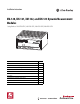
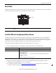
XM-12X Dynamic Measurement Modules
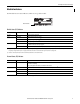
Channel 1, Channel 2, and Tachometer Status Indicator
Setpoint Multiplier Indicator
Relay Indicator
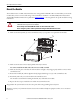
Self-Test
The XM-12x modules perform a self-test at powerup. The self-test includes a status indicator test and a device test. During
the status indicator test, the indicators turn on independently and in sequence for approximately 0.25 seconds.
The device test occurs after the status indicator test. The Module Status (MS) indicator is used to indicate the status of the
device self-test.
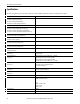
Color State Description
No color Off • Normal operation with alarm limits on the channel.
• No power applied to the module; look at Module Status indicator.
Yellow Solid An alert level alarm condition exists on the channel (and no transducer fault, tachometer fault, or danger level alarm condition
exists).
Flashing (tach status
indicator only)
Tachometer fault (no transducer fault) condition exists on the tachometer channel.
Red Solid A danger level alarm condition exists on the channel (and no transducer fault or tachometer fault condition exists).
Flashing A transducer fault condition exists on the channel.
Color State Description
Yellow Off Setpoint multiplier is not in effect.
Solid Setpoint multiplier is in effect.
Color State Description
Red Off On-board relay is not activated.
Solid On-board relay is activated.
MS Indicator State Description
Flashing red and green Device self-test is in progress.
Solid green or flashing green Device self-test completed successfully, and the firmware is valid and running.
Flashing red • Device self-test completed, the hardware is OK, but the firmware is invalid.
• The firmware download is in progress.
Solid red Unrecoverable fault, hardware failure, or Boot Loader program corruption.