Installation Instructions XM-120, XM-121, XM-122, and XM-123 Dynamic Measurement Modules Catalog Numbers 1440-VST02-01RA, 1440-VLF02-01RA, 1440-VSE02-01RA,1440-VAD02-01RA 1440-xxx02-01RA Topic Page Environment and Enclosure 3 European Hazardous Location Approval 4 North American Hazardous Location Approval 5 Mount the Module 6 Module Indicators 7 Self-Test 8 Reset Switch 9 Install the XM Serial Configuration Utility Software 9 Specifications 10 Additional Resources 12
XM-12X Dynamic Measurement Modules Important User Information Read this document and the documents listed in the additional resources section about installation, configuration, and operation of this equipment before you install, configure, operate, or maintain this product. Users are required to familiarize themselves with installation and wiring instructions in addition to requirements of all applicable codes, laws, and standards.
XM-12X Dynamic Measurement Modules Environment and Enclosure ATTENTION: This equipment is intended for use in a Pollution Degree 2 industrial environment, in overvoltage Category II applications (as defined in IEC 60664-1), at altitudes up to 2000 m (6562 ft) without derating. This equipment is not intended for use in residential environments and may not provide adequate protection to radio communication services in such environments. This equipment is supplied as open-type equipment.
XM-12X Dynamic Measurement Modules ATTENTION: The serial communication port is intended only for temporary local-programming purposes only and is not intended for permanent connection: • The serial cable and power connections are not to exceed 3.0 m (9.84 ft). • This product is intended to be mounted to a well-grounded mounting surface such as a metal panel or DIN rail. For DIN rail mounting, use zinc plated yellow-chromate steel DIN rail to assure proper grounding.
XM-12X Dynamic Measurement Modules North American Hazardous Location Approval The following information applies when operating this equipment in hazardous locations. Informations sur l'utilisation de cet équipement en environnements dangereux. Products marked "CL I, DIV 2, GP A, B, C, D" are suitable for use in Class I Division 2 Groups A, B, C, D, Hazardous Locations and nonhazardous locations only.
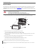
XM-12X Dynamic Measurement Modules Mount the Module The modules mount on a XM® 940 terminal base unit, catalog number 1440-TB-A. We recommend that you mount the modules after you have connected the wiring on the terminal base unit. Refer to the XM-940 Dynamic Measurement Terminal Base Installation Instructions, publication GMSI10-IN020, or the user guide for the specific module for wiring information. ATTENTION: The XM-12X modules are compatible only with the XM-940 terminal base unit.
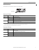
XM-12X Dynamic Measurement Modules Module Indicators Each module has seven status indicators, which are on top of the module. Module Indicators Module Status (MS) Indicator Color State Description No color Off No power applied to the module. Green Flashing Red Module performing power-up self-test. Flashing Module operating in Program mode.(1) Solid Module operating in Run mode.(2) Flashing • Application firmware is invalid or not loaded. Download firmware to the module.
XM-12X Dynamic Measurement Modules Channel 1, Channel 2, and Tachometer Status Indicator Color State Description No color Off • Normal operation with alarm limits on the channel. • No power applied to the module; look at Module Status indicator. Yellow Solid An alert level alarm condition exists on the channel (and no transducer fault, tachometer fault, or danger level alarm condition exists).
XM-12X Dynamic Measurement Modules Reset Switch The XM-12x modules have an external reset switch on top of the module. The Reset switch can be used to reset all latched relays in the relay expansion module when it is attached to an XM-12x module. Reset Switch IMPORTANT The Reset switch resets the relays only if the input is no longer in alarm or the condition that caused the alarm is no longer present.
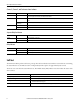
XM-12X Dynamic Measurement Modules Specifications The following table lists the technical specifications for the XM-120, XM-121, XM-122, and XM-123 modules.
XM-12X Dynamic Measurement Modules Attribute XM-120, XM-121, XM-122, and XM-123 Modules Isolation voltage 250V (continuous), Basic Insulation Type, relay to all other circuits. Isolation between other circuits is not rated.
Additional Resources These documents contain additional information concerning related products from Rockwell Automation. Resource Description 1440 XM Monitoring Modules Specifications Technical Data, publication 1440-TD001 Provides technical specifications for the 1440 series of monitoring modules.