
Owner's manual

Publication GMSI10-UM003D-EN-P - May 2010
47
1 Normal condition when the module is not a slave to an XM-440, PLC, or other master device.
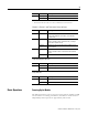
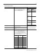
Channel 1, Channel 2, and Tachometer Status Indicators
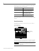
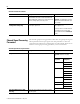
Setpoint Multiplier Indicator
Relay Indicator
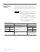
Basic Operations
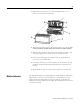
Powering Up the Module
The XM-123 performs a self-test at power-up. The self-test includes an LED
test and a device test. During the LED test, the indicators will be turned on
independently and in sequence for approximately 0.25 seconds.
Red Flashing One or more I/O connections are in the timed-out state.
Solid Failed communications (duplicate MAC ID or Bus-off).
Color State Description
No color Off • Normal operation within alarm limits on the channel.
• No power applied to the module, look at Module
Status LED.
Yellow Solid An alert level alarm condition exists on the channel
(and no transducer fault, tachometer fault, or danger
level alarm condition exists).
Flashing
(Tach LED only)
Tachometer fault (no transducer fault) condition exists
on the channel.
Red Solid A danger level alarm condition exists on the channel
(and no transducer fault or tachometer fault condition
exists).
Flashing A transducer fault condition exists on the channel.
Color State Description
Yellow Off Setpoint multiplier is not in effect.
Solid Setpoint multiplier is in effect.
Color State Description
Red Off On-board relay is not activated.
Solid On-board relay is activated.
Color State Description