
Owner's manual

Publication GMSI10-UM003D-EN-P - May 2010
22
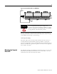
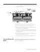
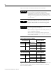
Table 2.1 shows the on-board relay connections for the XM-123.
Figures 2.9 and 2.10 illustrate the behavior of the NC and NO terminals when
the relay is wired for failsafe, alarm or nonalarm condition or non-failsafe,
alarm or nonalarm condition.
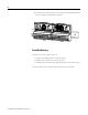
IMPORTANT
All XM relays are double pole. This means that each relay
has two contacts in which each contact operates
independently but identically. The following information
and illustrations show wiring solutions for both contacts;
although, in many applications it may be necessary to wire
only one contact.
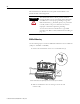
TIP
The Expansion Relay module may be connected to the
module to provide additional relays. Refer the XM-441
Expansion Relay Module User Guide for wiring details.
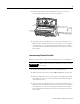
IMPORTANT
The NC/NO terminal descriptions (page 20) correspond
to a de-energized (unpowered) relay.
When the relay is configured for non-failsafe operation, the
relay is normally de-energized.
When the relay is configured for failsafe operation, the
relay is normally energized, and the behavior of the NC and
NO terminals is inverted.
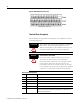
Table 2.1 Relay Connections for XM-123
Configured for
Failsafe Operation Relay 1 Terminals
Nonalarm Alarm Wire Contacts Contact 1 Contact 2
Closed Opened COM 47 50
NO 48 49
Opened Closed COM 47 50
NC 46 51
Configured for
Non-failsafe Operation Relay 1 Terminals
Nonalarm Alarm Wire Contacts Contact 1 Contact 2
Closed Opened COM 47 50
NC 46 51
Opened Closed COM 47 50
NO 48 49