
Owner's manual

Publication GMSI10-UM003D-EN-P - May 2010
20
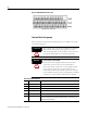
1 Terminals are internally connected and isolated from the Chassis terminals.
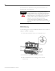
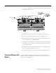
Connecting the Power Supply
Power supplied to the module must be nominally 24 Vdc (±10%) and must be
a Class 2 rated circuit.
Wire the DC-input power supply to the terminal base unit as shown in Figure
2.8.
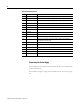
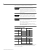
35 Chassis Connection to DIN rail ground spring or panel mounting hole
36 Chassis Connection to DIN rail ground spring or panel mounting hole
37 Chassis Connection to DIN rail ground spring or panel mounting hole
38 Chassis Connection to DIN rail ground spring or panel mounting hole
39 SetPtMult Switch input to activate Set Point Multiplication (active closed)
40 Switch RTN Switch return, shared between SetPtMult and Reset Relay
41 Reset Relay Switch input to reset internal relay (active closed)
42 Reserved
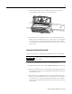
43
24 V Common
1
Internally DC-coupled to circuit ground
44 +24 V In Connection to primary external +24 V power supply, positive side
45
24 V Common
1
Connection to external +24 V power supply, negative side (internally
DC-coupled to circuit ground)
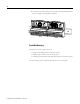
46 Relay N.C. 1 Relay Normally Closed contact 1
47 Relay Common 1 Relay Common contact 1
48 Relay N.O. 1 Relay Normally Open contact 1
49 Relay N.O. 2 Relay Normally Open contact 2
50 Relay Common 2 Relay Common contact 2
51 Relay N.C. 2 Relay Normally Closed contact 2
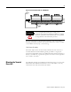
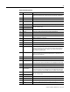
Terminal Block Assignments
No. Name Description