
Manual

Publication GMSI10-UM008D-EN-P - August 2010
21
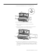
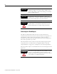
Connecting the Power Supply
The power supply to the module is nominally 24V dc (±10%) and must be a
Class 2 rated circuit.
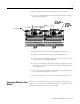
Wire the DC-input power supply to the terminal base unit as shown in Figure
2.8.
Figure 2.8 DC Input Power Supply Connections
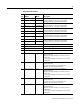
40 Common Internally DC-coupled to circuit ground
41 Chassis Connection to DIN rail ground spring or panel mounting hole
42 Chassis Connection to DIN rail ground spring or panel mounting hole
43 Chassis Connection to DIN rail ground spring or panel mounting hole
44 CAN_High DeviceNet bus connection, high differential (white wire)
45 CAN_Low DeviceNet bus connection, low differential (blue wire)
46 CAN Shield DeviceNet bus connection to chassis ground (bare wire)
47 DNet V (+) DeviceNet bus power input, positive side (red wire)
48 DNet V (-) DeviceNet bus power input, negative side (black wire)
49 4-20 mA 4 (-) 4-20 mA output 4, negative side
50 4-20 mA 5 (-) 4-20 mA output 5, negative side
51 4-20 mA 6 (-) 4-20 mA output 6, negative side
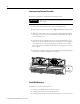
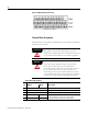
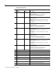
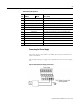
Terminal Block Assignments
Name
No. XM-361 XM-362 Description
-
24V dc
Power
Supply
+
-