XM-361/362 Temperature Module User Guide Firmware Revision 5 1440-TUN06-00RE, 1440-TTC06-00RE
Important User Information Solid state equipment has operational characteristics differing from those of electromechanical equipment. Safety Guidelines for the Application, Installation and Maintenance of Solid State Controls (publication SGI-1.1 available from your local Rockwell Automation sales office or online at http://literature.rockwellautomation.com) describes some important differences between solid state equipment and hardwired electromechanical devices.
Safety Approvals The following information applies when operating this equipment in hazardous locations. Informations sur l’utilisation de cet équipement en environnements dangereux. Products marked "CL I, DIV 2, GP A, B, C, D" are suitable for use in Class I Division 2 Groups A, B, C, D, Hazardous Locations and nonhazardous locations only. Each product is supplied with markings on the rating nameplate indicating the hazardous location temperature code.
Table of Contents Chapter 1 Introduction Introducing the XM-361 and XM-362 Modules. . . . . . . . . . . . . . . . . . . 1 XM-361 and XM-362 Module Components . . . . . . . . . . . . . . . . . . . . . 2 Using this Manual. . . . . . . . . . . . . . . . . . . . . . . . . . . . . . . . . . . . . . . . . . . 3 Organization. . . . . . . . . . . . . . . . . . . . . . . . . . . . . . . . . . . . . . . . . . . . 3 Document Conventions . . . . . . . . . . . . . . . . . . . . . . . . . . . . . . . . . .
vi Appendix A Specifications . . . . . . . . . . . . . . . . . . . . . . . . . . . . . . . . . . . . . . . . . . . . . . . . . . . . . . . . . 65 Appendix B DeviceNet Information Electronic Data Sheets. . . . . . . . . . . . . . . . . . . . . . . . . . . . . . . . . . . . . . 71 Changing Operation Modes. . . . . . . . . . . . . . . . . . . . . . . . . . . . . . . . . . 71 Transition to Program Mode. . . . . . . . . . . . . . . . . . . . . . . . . . . . . . 72 Transition to Run Mode . . . . . . . . . . .
vii Parameter Object (Class ID 0FH). . . . . . . . . . . . . . . . . . . . . . . . . . . . . 97 Class Attributes . . . . . . . . . . . . . . . . . . . . . . . . . . . . . . . . . . . . . . . . 97 Instances. . . . . . . . . . . . . . . . . . . . . . . . . . . . . . . . . . . . . . . . . . . . . . 97 Instance Attributes. . . . . . . . . . . . . . . . . . . . . . . . . . . . . . . . . . . . . . 99 Services . . . . . . . . . . . . . . . . . . . . . . . . . . . . . . . . . . . . . . . . . . . . . .
viii Publication GMSI10-UM008D-EN-P - August 2010
Chapter 1 Introduction This chapter provides an overview of the XM-361 Universal Temperature and the XM-362 Isolated Thermocouple Temperature modules. It also discusses the components of the modules.
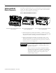
2 XM-361 and XM-362 Module Components The XM-361 and XM-362 consist of a terminal base unit and an instrument module. The XM-361 and XM-362 Temperature modules and the XM-944 Temperature Terminal Base are shown below. Figure 1.1 XM-361/362 Module Components TEMPERATURE XM-944 Temperature Module Terminal Base Unit Cat. No. 1440-TB-E 1440-TUN06-00RE XM-361 Universal Temperature Module Cat. No. 1440-TUN06-00RE ISOLATED TEMPERA TURE 1440-TTC06-00RE XM-362 Isolated Thermocouple Temperature Module Cat.
3 Using this Manual This manual introduces you to the XM-361 and XM-362 Temperature modules. It is intended for anyone who installs, configures, or uses the XM-361 and XM-362 Temperature modules. Organization To help you navigate through this manual, it is organized in chapters based on these tasks and topics. Chapter 1 "Introduction" contains an overview of this manual and the XM-361 and XM-362 modules.
4 EXAMPLE Publication GMSI10-UM008D-EN-P - August 2010 This convention presents an example.
Chapter 2 Installing the XM-361/362 Temperature Modules This chapter discusses how to install and wire the XM-361 and XM-362 Temperature modules. It also describes the module indicators and the basic operations of the modules.
6 XM Installation Requirements This section describes requirements and considerations for an XM system. System Wiring Requirements Use solid or stranded wire. All wiring should meet the following specifications: • 14 to 22 AWG copper conductors without pretreatment; 8 AWG required for grounding the DIN rail for electromagnetic interference (emi) purposes • Recommended strip length 8 millimeters (0.
7 When using a 3-wire configuration, the XM-361 compensates for resistance error due to lead wire length. For example, in a 3-wire configuration, the XM-361 reads the resistance due to the length of the wires and assumes that the resistance of the other wire is equal. If the resistance of the individual lead wires is much different, an error may exist. The closer the resistance values are to each other, the greater the amount of error is eliminated.
8 Figure 2.
9 IMPORTANT See Application Technique "XM Power Supply Solutions", publication ICM-AP005A-EN-E, for guidance in architecting power supplies for XM systems. Grounding Requirements Use these grounding requirements to ensure safe electrical operating circumstances, and to help avoid potential emi and ground noise that can cause unfavorable operating conditions for your XM system. DIN Rail Grounding The XM modules make a chassis ground connection through the DIN rail.
10 Figure 2.2 XM System DIN Rail Grounding 1 1440-VST02-01RA DYNAMIC MEASUREMENT 1440-REX00-04RD EXPANSION RELAY 1440-VST02-01RA DYNAMIC MEASUREMENT 1440-REX00-04RD EXPANSION RELAY Power Supply 1440-RMA00-04RC MASTER RELAY 1 1440-REX00-04RD EXPANSION RELAY 1440-VST02-01RA DYNAMIC MEASUREMENT 1440-TSP02-01RB POSITION 1440-REX00-04RD EXPANSION RELAY 1440-REX00-04RD EXPANSION RELAY 1440-VST02-01RA DYNAMIC MEASUREMENT 1440-REX00-04RD EXPANSION RELAY Power Supply 1 Use 14 AWG wire.
11 Figure 2.3 DIN Rail Grounding Block Panel/Wall Mount Grounding The XM modules can also be mounted to a conductive mounting plate that is grounded. See Figure 2.5. Use the grounding screw hole provided on the terminal base to connect the mounting plate the Chassis terminals. Figure 2.
12 Figure 2.5 Panel/Wall Mount Grounding 1 Power Supply 1 Power Supply 1 Publication GMSI10-UM008D-EN-P - August 2010 Use 14 AWG wire.
13 24 V Common Grounding 24 V power to the XM modules must be grounded. When two or more power supplies power the XM system, ground the 24 V Commons at a single point, such as the ground bus bar. IMPORTANT IMPORTANT If it is not possible or practical to ground the -24Vdc supply, then it is possible for the system to be installed and operate ungrounded. However, if installed ungrounded then the system must not be connected to a ground through any other circuit unless that circuit is isolated externally.
14 ATTENTION Use of a separate DeviceNet power supply is not permitted. See Application Technique "XM Power Supply Solutions", publication ICM-AP005A-EN-E, for guidance in using XM with other DeviceNet products. For more information on the DeviceNet installation, refer to the ODVA Planning and Installation Manual - DeviceNet Cable System, which is available on the ODVA web site (http://www.odva.org).
15 1. Position the terminal base on the 35 x 7.5 mm DIN rail (A). Position terminal base at a slight angle and hook over the top of the DIN rail. 2. Slide the terminal base unit over leaving room for the side connector (B). 3. Rotate the terminal base onto the DIN rail with the top of the rail hooked under the lip on the rear of the terminal base. 4. Press down on the terminal base unit to lock the terminal base on the DIN rail.
16 Interconnecting Terminal Base Units Follow the steps below to install another terminal base unit. IMPORTANT Make certain you install the terminal base units in order of left to right. 1. Position the terminal base on the 35 x 7.5 mm DIN rail (A). 2. Make certain the side connector (B) is fully retracted into the base unit. 3. Slide the terminal base unit over tight against the neighboring terminal base. Make sure the hook on the terminal base slides under the edge of the terminal base unit. 4.
17 Use the following steps to install the terminal base on a wall or panel. 1. Lay out the required points on the wall/panel as shown in the drilling dimension drawing below. Side Connector 2. Drill the necessary holes for the #6 self-tapping mounting screws. 3. Secure the terminal base unit using two #6 self-tapping screws. 4. To install another terminal base unit, retract the side connector into the base unit. Make sure it is fully retracted. 5.
18 Figure 2.7 XM-944 Terminal Base Unit XM-944, Cat. No. 1440-TB-E Terminal Block Assignments The terminal block assignments and descriptions for the XM-361 and XM-362 modules are shown below. ATTENTION WARNING The terminal block assignments are different for different XM modules. The following table applies only to the Temperature modules. Refer to the installation instructions for the specific XM module for its terminal assignments.
19 Terminal Block Assignments Name No.
20 Terminal Block Assignments Name No.
21 Terminal Block Assignments Name No.
22 IMPORTANT IMPORTANT ATTENTION A Class 2 circuit can be provided by use of an NEC Class 2 rated power supply, or by using a SELV or PELV rated power supply with a 5 Amp current limiting fuse installed before the XM module(s). 24Vdc needs to be wired to terminal 37 (+24 V In) to provide power to the device and other XM modules linked to the wired terminal base via the side connector. The power connections are different for different XM modules.
23 Figure 2.9 4-20 mA Output Connections Figure 2.10 4-20 mA Output Connections cont.
24 Connecting a Remote Relay Reset Signal If you set the relay to latching and the relay activates, the relay stays activated even when the condition that caused the alarm has ended. The remote relay reset signal enables you to reset the relay remotely after you have corrected the alarm condition. The Temperature modules do not have an on-board relay. The relays are added when an Expansion Relay (XM-441) module is connected to the Temperature modules.
25 Figure 2.11 Remote Relay Reset Signal Connection 1Ω, 1%, 1/4 or 1/2 W resistor ATTENTION The switch power supply is isolated, but shares common with Channel 4 and Channel 5 4-20 mA outputs. Care should be taken as to how these are grounded, if at all. A single switch contact can also be shared by multiple Temperature modules wired in series as shown in Figure 2.12.
26 Figure 2.12 Typical Multiple XM Modules Remote Relay Reset Signal Connection 1Ω resistor XM-361 Module Sensor Wiring The XM-361 accepts inputs from Thermocouples and 2-wire and 3-wire RTDs. Note that all six channels can be any mix of RTDs and thermocouple inputs. Connecting a Thermocouple Figure 2.13 shows the wiring of thermocouples to the terminal base unit of the XM-361 module.
27 Figure 2.13 Thermocouple to XM-361 wiring TYPICAL WIRING FOR THERMOCOUPLES TO XM-361 TEMPERATURE MODULE 24V dc + Power - Supply 37 38 within +/- 3V dc ungrounded thermocouple + IN 5+ IN 5 - 25 26 27 28 29 30 IN 4+ IN 4 - + - IN 6+ IN 6 - grounded thermocouple + - - within +/- 3V dc grounded thermocouple Connecting a 3-Wire RTD The XM-361 has variable gain circuitry that delivers the best possible range and resolution for a given application.
28 Figure 2.14 3-wire RTD to Channel 1 Wiring TYPICAL WIRING FOR 3-WIRE RTD TO XM-361 TEMPERATURE MODULE CHANNEL 1 19 20 RTD RTD + RTD - 3 41 3-wire RTD Shield Figure 2.
29 Figure 2.16 3-wire RTD to Channel 3 Wiring TYPICAL WIRING FOR 3-WIRE RTD TO XM-361 TEMPERATURE MODULE CHANNEL 3 42 23 24 RTD RTD + RTD - 7 3-wire RTD Shield Figure 2.
30 Figure 2.18 3-wire RTD to Channel 5 Wiring TYPICAL WIRING FOR 3-WIRE RTD TO XM-361 TEMPERATURE MODULE CHANNEL 5 Shield 43 27 28 RTD RTD + RTD - 11 3-wire RTD Figure 2.
31 Connecting a 2-Wire RTD Figures 2.20 to 2.25 show the wiring of 2-wire RTDs to the terminal base unit of the XM-361 module. ATTENTION You may ground the cable shield at either end of the cable. Do not ground the shield at both ends. Recommended practice is to ground the cable shield at the XM-361 terminal base and not at the field device. Any convenient Chassis terminal may be used (see Terminal Block Assignments on page 18). Figure 2.
32 Figure 2.21 2-wire RTD to Channel 2 Wiring TYPICAL WIRING FOR 2-WIRE RTD TO XM-361 TEMPERATURE MODULE CHANNEL 2 21 22 RTD RTD + 5 41 Shield 2-wire RTD Figure 2.
33 Figure 2.23 2-wire RTD to Channel 4 Wiring TYPICAL WIRING FOR 2-WIRE RTD TO XM-361 TEMPERATURE MODULE CHANNEL 4 Shield 42 25 26 RTD RTD + 9 2-wire RTD Figure 2.
34 Figure 2.25 2-wire RTD to Channel 6 Wiring TYPICAL WIRING FOR 2-WIRE RTD TO XM-361 TEMPERATURE MODULE CHANNEL 6 Shield 43 29 30 13 RTD RTD + 2-wire RTD Connecting a 4-Wire RTD Figures 2.26 to 2.31 show the wiring of 4-wire RTDs to the terminal base unit of the XM-361 module. Wiring of a 4-wire RTD is exactly the same as the 3-wire RTD with one wire left open. ATTENTION Publication GMSI10-UM008D-EN-P - August 2010 You may ground the cable shield at either end of the cable.
35 Figure 2.26 4-wire RTD to Channel 1 Wiring TYPICAL WIRING FOR 4-WIRE RTD TO XM-361 TEMPERATURE MODULE CHANNEL 1 Leave one wire open. 19 20 RTD RTD + RTD - 3 41 4-wire RTD Shield Figure 2.27 4-wire RTD to Channel 2 Wiring TYPICAL WIRING FOR 4-WIRE RTD TO XM-361 TEMPERATURE MODULE CHANNEL 2 Leave one wire open.
36 Figure 2.28 4-wire RTD to Channel 3 Wiring TYPICAL WIRING FOR 4-WIRE RTD TO XM-361 TEMPERATURE MODULE CHANNEL 3 Leave one wire open. 42 23 24 RTD RTD + 7 RTD - 4-wire RTD Shield Figure 2.29 4-wire RTD to Channel 4 Wiring TYPICAL WIRING FOR 4-WIRE RTD TO XM-361 TEMPERATURE MODULE CHANNEL 4 Leave one wire open.
37 Figure 2.30 4-wire RTD to Channel 5 Wiring TYPICAL WIRING FOR 4-WIRE RTD TO XM-361 TEMPERATURE MODULE CHANNEL 5 Leave one wire open. Shield 43 27 28 11 RTD RTD + RTD - 4-wire RTD Figure 2.31 4-wire RTD to Channel 6 Wiring TYPICAL WIRING FOR 4-WIRE RTD TO XM-361 TEMPERATURE MODULE CHANNEL 6 Shield 43 Leave one wire open.
38 XM-362 Module Sensor Wiring The XM-362 accepts inputs only from Thermocouples. All six input channels are electrically isolated from each other and from circuit power and ground. The isolation provided is up to 250 V. IMPORTANT With all the cable shields connected (six individual input cables and six output cables), there are not enough chassis terminals for each shield. Therefore, the cable shields should be paired as depicted in the following illustrations.
39 IMPORTANT IMPORTANT When using grounded and/or exposed thermocouples that are touching electrically conductive material, the ground potential between any two channels cannot exceed +250 Volts. Exceeding this voltage could cause permanent damage. Inside the XM-361 and XM-362 terminal bases are cold junction sensors used to determine the thermocouple measurements. These sensors have intelligent diagnostics that can determine cold junction out-of-range (OOR) conditions and hardware failures.
40 A special cable (Cat. No. 1440-SCDB9FXM2) is required for this serial connection. The connector that inserts into the PC is a DB-9 female connector, and the connector that inserts into the module is a USB Mini-B male connector. WARNING IMPORTANT If you connect or disconnect the serial cable with power applied to the module or the serial device on the other end of the cable, an electrical arc can occur. This could cause an explosion in hazardous location installations.
41 IMPORTANT The DeviceNet power circuit through the XM module interconnect, which is rated at only 300 mA, is not intended or designed to power DeviceNet loads. Doing so could damage the module or terminal base. To preclude this possibility, even unintentionally, it is recommended that DeviceNet V+ be left unconnected. ATTENTION ATTENTION ATTENTION IMPORTANT You must ground the DeviceNet shield at only one location.
42 Mounting the Module The XM-361 and XM-362 mount on the XM-944 terminal base unit, Cat. No. 1440-TB-E. You should mount the module after you have connected the wiring on the terminal base unit. ATTENTION The XM-361 and XM-362 are compatible only with the XM-944 terminal base unit. The keyswitch on the terminal base unit should be at position 5 for the modules. Do not attempt to install XM-361 and XM-362 modules on other terminal base units.
43 2. Make certain the side connector (B) is pushed all the way to the left. You cannot install the module unless the connector is fully extended. 3. Make sure that the pins on the bottom of the module are straight so they will align properly with the connector in the terminal base unit. 4. Position the module (D) with its alignment bar (E) aligned with the groove (F) on the terminal base. 5. Press firmly and evenly to seat the module in the terminal base unit.
44 Module Status (MS) Indicator Color State Description No color Off No power applied to the module. Green Flashing Red Module performing power-up self test. Flashing Module operating in Program Mode1. Solid Module operating in Run Mode2. Flashing • Application firmware is invalid or not loaded. Download firmware to the module. Red • Firmware download is currently in progress. • The module power voltage is incorrect. Solid An unrecoverable fault has occurred.
45 Channel Status Indicator (6 in all) Color State Description No Color Off • Normal operation within alarm limits on the channel. • No power applied to the module, look at Module Status LED. Basic Operations Yellow Solid An alert level alarm condition exists on the channel (and no sensor-out-of-range or danger level alarm condition exists). Red Solid A danger level alarm condition exists on the channel (and no sensor-out-of-range condition exists).
46 Figure 2.35 Reset Switch Press the Reset Switch to reset the relays The switch can be used to reset all latched relays in the Expansion Relay module when it is connected to the XM-361 or XM-362. IMPORTANT Publication GMSI10-UM008D-EN-P - August 2010 The Reset switch resets the relays only if the input is no longer in alarm or the condition that caused the alarm is no longer present.
Chapter 3 Configuration Parameters This chapter provides a complete listing and description of the XM-361 and XM-362 parameters. The parameters can be viewed and edited using the XM Serial Configuration Utility software and a personal computer. If the module is installed on a DeviceNet network, configuring can also be performed using a network configuration tool such as RSNetWorx (Version 3.0 or later). Refer to your configuration tool documentation for instructions on configuring a device.
48 General Parameters Use the general parameters to configure the units of temperature that will be used by the XM-361 and XM-362 modules and to enable the relay reset switch terminals on theses modules. The general parameters in the EDS file also show the cold junction temperature and whether the cold junction temperature is over or underrange. General Parameters Parameter Name Description Values/Comments Temperature Units Sets the temperature units for the module.
49 Channel Parameters Parameter Name Description Values/Comments Channel Name (XM Serial Configuration Utility only) A descriptive name to help identify the channel in the XM Serial Configuration Utility Maximum 18 characters Sensor Type Sets the type of temperature sensor for the channel.
50 Channel Parameters Parameter Name Description Values/Comments Rate Time Constant The time constant used for smoothing (low-pass filtering) of the rate value. Seconds Note: The greater the rate time constant, the slower the response of the measured rate of change in the input signal (less sensitive to noise in the signal). Alarm Parameters The Alarm parameters control the operation of the alarms (alert and danger level) and provide alarm status. The XM-361 and XM-362 provide a total of 12 alarms.
51 Alarm Parameters Parameter Name Description Values/Comments Condition Controls when the alarm should trigger. Options: Greater Than Less Than Inside Range Outside Range • Greater than - Triggers the alarm when the measurement value is greater than or equal to the Alert and Danger Threshold values. The Danger Threshold value must be greater than or equal to the Alert Threshold value for the trigger to occur.
52 Alarm Parameters Parameter Name Description Values/Comments Alert Threshold (Low) The lesser threshold value for the alert (alarm) condition. Danger Threshold (Low) The lesser threshold value for the danger (shutdown) condition. Hysteresis The amount that the measured value must fall (below the threshold) before the alarm condition is cleared. For example, Alert Threshold = 120 and Hysteresis = 2.
53 Relay Parameters Parameter Name Description Options/Comments Number (XM Serial Configuration Utility only) Sets the relay to be configured in the XM Serial Configuration Utility. The relays are either relays on the Expansion Relay module when it is connected to the XM-361 or XM-362 or virtual relays. Virtual relays are non-physical relays. Use them when you want the effect of the relay (monitor alarms, delay, and change status) but do not need an actual contact closure.
54 Relay Parameters Parameter Name Description XM Configuration EDS File Utility Activation Logic Logic XM Configuration EDS File Utility Alarm A/B Alarm Identifier A/B Options/Comments Options: A only A or B A and B • A or B - Relay is activated when either Alarm A or Alarm B meets or exceeds the selected Alarm Status condition(s). • A and B - Relay is activated when both Alarm A and Alarm B meet or exceed the selected Alarm Status condition(s).
55 Relay Parameters Parameter Name Description Options/Comments Sets the alarm conditions that will cause the relay to Options: Normal Danger activate. You can select more than one. Sensor OOR Alert • Normal The current measurement is not within Alarm Levels Disarm excess of any alarm thresholds. Module Fault • Alert - The current measurement is in excess of the alert level threshold(s) but not in excess of the Check to enable. danger level threshold(s).
56 Relay Parameters Parameter Name Description XM Configuration EDS File Utility Failsafe Relay Failsafe Option Determines whether the relay is failsafe or non-failsafe. Failsafe operation means that when in alarm, the relay contacts are in their "normal," de-energized, or "shelf-state" positions. In other words, normally closed relays are closed in alarm, and normally open relays are open in alarm. With failsafe operation, a power failure equals an alarm.
57 4-20 mA Output Parameters The 4-20 mA output parameters define the characteristics of the 4-20 mA output signals. The XM-361 and XM-362 support a total of six 4-20 mA outputs. Each output is permanently associated with a corresponding channel. The parameters are the same for each output. IMPORTANT If the Enable Relay Reset Switch Terminals parameter is enabled, Channel 6 is not available for configuration, and the Channel 6 4-20 mA output is set to a fixed (12 mA) level.
58 IMPORTANT The 4-20 mA outputs are either on or off. When they are on, the 4-20 mA outputs overshoot the 4 and 20 mA limits by 10% when the measurement exceeds the minimum and maximum range. This means the minimum current produced is 3.6 mA and the maximum current produced is 22 mA. When the 4-20 mA outputs are off, they produce a current approximately 2.9 mA. The 4-20 mA outputs are off under the following conditions: • The 4-20 mA outputs are set to "Disable" (see Enable above).
59 trend records, the interval between trend records, and which relay triggers (activates) the collection of the trend data. IMPORTANT The Triggered Trend parameters are not included in the EDS file and cannot be edited using generic configuration tools such as RSNetWorx for DeviceNet. Triggered Trend Parameters Parameter Name Description Values/Comments Enable Triggered Trend Measurements Enables/disables the triggered trend measurements. Select to configure the triggered trend measurements.
60 Triggered Trend Parameters Parameter Name Description Values/Comments Post Trigger The percentage of records to be collected once the trigger occurs. For example, if you set Post Trigger to 20%, then 80% of the records in the trend are before the trigger occurs, and 20% of the records in the trend are after the trigger occurs. 0 to 100 Percent This allows you to evaluate what happened after the trigger occurred. Status Shows the status of the trend data.
61 I/O Data Parameters The I/O data parameters are used to configure the content and size of the DeviceNet I/O Poll response message. IMPORTANT The XM-361 and XM-362 must be free of Poll connections when configuring the Poll Output (Poll Response Assembly) and Poll Size. Any attempt to download the parameters while a master device has established the Poll connection with the XM-361 or XM-362 will result in an error.
62 The Data parameters are used to view the measured values of the input channels and the 4–20 mA outputs, as well as to monitor the status of the channels, alarms, and relays. Data Parameters TIP To view all the data parameters in the XM Serial Configuration Utility, click the View Data tab. Channel Data Parameters Channel Data Parameters Parameter Name Description Values/Comments Channel Status States whether a fault exists on the associated channel.
63 Alarm and Relay Status Parameters Alarm and Relay Status Parameters Parameter Name Description Values/Comments Alarm Status States the current status of the measurement value and rate of change alarm. Possible status values: States the current status of the relay.
64 Device Mode Parameters The Device Mode parameters are used to control the functions and the behavior of the device. IMPORTANT The XM Serial Configuration Utility handles these parameters automatically and transparently to the user. Device Mode Parameters Parameter Name Description Values/Comments Device Mode Sets the current operation mode of the device. Refer to Changing Operation Modes on page 71 for more information. Options: Run Mode Program Mode Autobaud Enables/disables autobaud.
Appendix A Specifications Appendix A lists the technical specifications for the XM-361/362 Temperature modules. XM-361/362 Technical Specifications Product Feature Specification Communications DeviceNet Standard DeviceNet protocol for all functions NOTE: The XM-361/362 use only the DeviceNet protocol, not power. Module power is provided independently.
66 XM-361/362 Technical Specifications Product Feature Specification Inputs Channels 1 to 6 RTD or thermocouple transducer signals, user configurable XM-361 accepts RTD and thermocouple inputs XM-362 accepts thermocouple inputs only Supported Thermocouple Types Type Range C° Range F° B 0°C to 1810°C (32°F to 3290°F) C 0°C to 1316°C (32°F to 2400°F) E 5°C to 284°C (41°F to 543°F) J 0°C to 364°C (32°F to 687°F) K -40°C to 484°C (-40°F to 903°F) N -40°C to 620°C (-40°F to 1148°F) R -40
67 XM-361/362 Technical Specifications Product Feature Specification RTD Current Source Value 1.004 mA ±1% Isolation Up to 250 volts of isolation for each input (XM-362 only) Common Mode Input Voltage ±3 Volts (XM-361 only) Input Impedance XM-361: 1 Mohm voltage input XM-362: 10 k voltage input Outputs 4-20 mA Outputs Two isolated banks of three outputs (one per channel) 600 ohm max load Accuracy ±1% of full scale max ±0.
68 XM-361/362 Technical Specifications Product Feature Specification Measured Parameters Measured Value Rate of Change Per minute Updated once per second Delta Time Buffer Number of Records 2048 Delta Time Interval 1 to 3600 seconds Trigger Mode Relay on an XM-441 Expansion Relay module is activated, or by a trigger event (for example, DeviceNet command from a controller or host). The data collected in the buffer is user configurable in software.
69 XM-361/362 Technical Specifications Product Feature Specification Relays Number Up to eight relays when interconnected to one or two XM-441 Expansion Relay modules, or Eight virtual relays whose status can be used by remote Control Systems Failsafe Normally energized (failsafe), or Normally de-energized (non-fail-safe) Latching Latching, or Non-latching Time Delay 0 to 25.
70 XM-361/362 Technical Specifications Product Feature Specification Environmental Operating Temperature -20 to +65°C (-4 to +149°F) Storage Temperature -40 to +85°C (-40 to +185°F) Relative Humidity 95% non-condensing Conformal Coating All printed circuited boards are conformally coated in accordance with IPC-A-610C. Physical Dimensions Height: 3.8 in (97 mm) Width: 3.7 in (94 mm) Depth: 3.7 in (94 mm) Terminal Screw Torque 7 pound-inches (0.
Appendix B DeviceNet Information Electronic Data Sheets Electronic Data Sheet (EDS) files are simple text files used by network configuration tools such as RSNetWorx (Version 3.0 or later) to help you identify products and easily commission them on a network. The EDS files describe a product’s device type, product revision, and configurable parameters on a DeviceNet network. The EDS files for the XM modules are installed on your computer with the XM configuration software.
72 Transition to Program Mode Parameter values can only be downloaded to an XM module while the module is in Program mode. Any attempt to download a parameter value while the module is in Run mode will result in a Device State Conflict error. To transition an XM module from Run mode to Program mode on a DeviceNet network, set the Device Mode parameter to "Program mode" and click Apply. Note that you cannot change any other parameter until you have downloaded the Program mode parameter.
73 The table below defines the services supported by the XM modules. The table includes the service codes, classes, instances, and attributes by their appropriate hexadecimal codes. Use the Class Instance Editor in RSNetWorx to execute these services, as illustrated in the following example.
74 Example To save the configuration parameters to the non-volatile memory (EEPROM), fill in the Class Instance Editor as shown below. Clear Send the attribute ID and then enter the Class (320 hex) and Instance (1) Select the Save service code Click Execute to initiate the action Invalid Configuration Errors A Start or Save service request to an XM module may return an Invalid Device Configuration error when there is a conflict amongst the configuration settings.
75 Additional Error Codes returned with the Invalid Device Configuration Error (0xD0) XM-361/362 I/O Message Formats Error Code (Hex) Description 0A Too many alarms associated with a single measurement. 0B Invalid node address in the alarm list. 0C Too many alarms in the alarm list. Or, no alarms in the alarm list. 0D Alarm levels cannot be zero for alarms that are enabled. 0E Too many slaves in the scanner’s input data table.
76 The Poll response data can also be requested explicitly through Assembly Object (Class ID 0x4), Instance 101 (0x65) – 103 (0x67), Data Attribute (3). The following tables show the static data format of Assembly instance 101– 103.
77 XM-361/362 Assembly Instance 103 Data Format Byte Definition 0–3 Channel 1 measurement value 4–7 Channel 1 rate of change value 8-11 Channel 2 measurement value 12-15 Channel 2 rate of change value 16-19 Channel 3 measurement value 20-23 Channel 3 rate of change value 24-27 Channel 4 measurement value 28-31 Channel 4 rate of change value 32-35 Channel 5 measurement value 36-39 Channel 5 rate of change value 40-43 Channel 6 measurement value 44-47 Channel 6 rate of change value
78 XM Status Values The following tables describe the XM Status values that are included in the COS messages.
79 Figure B.1 Bit-Strobe Command The XM modules use the bit received in a Bit-Strobe connection as a trigger event. When the bit number corresponding to the XM module’s node address is set, the XM module will collect the triggered trend data. Note that the XM modules do not send data in the Bit-Strobe response. ADR for XM Modules Automatic Device Replacement (ADR) is a feature of an Allen-Bradley DeviceNet scanner.
80 • The ADR scanner can not download the configuration data to an XM module if the module has a saved configuration in its non-volatile memory. This happens because the saved configuration is restored and the module enters Run mode when the power is cycled. (Configuration parameters cannot be downloaded while an XM module is in Run mode.) XM modules must be in Program mode for the ADR configuration to be downloaded and this occurs only when there is no saved configuration.
81 – All SU/CD Trend related parameters – Custom Assembly structure (see page 61) • The ADR and trigger group functions cannot be used together. A module can have only one primary master so a module cannot be both configured for ADR and included in a trigger group. The ADR scanner must be the primary master for the modules configured for ADR. The XM-440 Master Relay module must be the primary master for modules included in a trigger group.
82 Publication GMSI10-UM008D-EN-P - August 2010
Appendix C DeviceNet Objects Appendix C provides information on the DeviceNet objects supported by the XM-361 and XM-362 modules.
84 The Identity Object provides identification and general information about the device. Identity Object (Class ID 01H) Class Attributes The Identity Object provides no class attributes. Instance Attributes Table C.
85 Table C.2 Identity Object Status Bit Name Description 4 Boot Program Vendor-specific, indicates that the boot program is running. The Main Application must be corrupt or missing. 5-7 Vendor-specific, not implemented 8 Minor Recoverable Fault Set whenever there is a sensor out of range. Also set if the ambient temperature is measured to be outside of the module’s operating range.
86 Class Attributes Table C.4 DeviceNet Object Class Attributes Attr ID Access Rule Name Data Type Default Value 1 Get Revision UINT 2 Instance Attributes Table C.
87 Services Table C.6 DeviceNet Object Services Service Code Class/Instance Usage Name 0Eh Class/Instance Get_Attribute_Single 10h Instance Set_Attribute_Single1 4Bh Instance Allocate_Master/Slave_Connetion_Set 4Ch Instance Release_Group_2_Identifier_Set 1 Attributes can only be set while the device is in Program Mode. See the description of the Device Mode Object for more information.
88 Table C.8 Assembly Object Instances Instance Name Type Description 101 Default Poll Response Message Input Measurement values 102 - 103 Alternate Poll Response Message Input Measurement values 199 Alternate Dynamic Poll Response Message Input User configurable measurement values and configuration parameters Instance Attributes Table C.
89 Table C.
90 Instance 102 - Measurement Values This assembly instance can be selected to be sent in response to an I/O Poll request from a Master. Table C.
91 Table C.
92 Table C.
93 Instances Table C.16 Connection Object Instances Instance Description 1 Explicit Message Connection for pre-defined connection set 2 I/O Poll Connection 3 I/O Strobe Connection 4 I/O COS (change of state) Connection 11 - 17 Explicit Message Connection Instance Attributes Table C.17 Connection Object Instance Attributes Attr ID Access Rule Name Data Type Description 1 Get State USINT State of the object. 2 Get Instance Type USINT Indicates either I/O or Messaging Connection.
94 Table C.17 Connection Object Instance Attributes Attr ID Access Rule 15 Name Data Type Description Get Consumed Connection Path Length UINT Number of bytes in the consumed_connection_path attribute. 16 Get Consumed Connection Path Array of USINT Specifies the Application Object(s) that are to receive the data consumed by this Connection Object. See DeviceNet Specification Volume 1 Appendix I. 17 Get Production Inhibit Time UINT Defines minimum time between new data production.
95 Instances Table C.20 Analog Input Point Object Instances Instance Name Description 1 Channel 1 Measurements Temperature measurement and Rate of Change for channel 1. 2 Channel 2 Measurements Temperature measurement and Rate of Change for channel 2. 3 Channel 3 Measurements Temperature measurement and Rate of Change for channel 3. 4 Channel 4 Measurements Temperature measurement and Rate of Change for channel 4.
96 Table C.21 Analog Input Point Object Class Attributes Attr ID Access Rule Name Data Type Description 113 Get/Set Sensor Type BYTE Specifies the sensor type.
97 The Parameter Object provides the interface to the XM-361 and XM-362 configuration data. There are 38 Parameter Object instances implemented in the XM-361 and XM-362 modules. Parameter Object (Class ID 0FH) Parameter Object instances 1-22 and 31-36 are implemented to provide an alternate method of setting the configuration parameters with EPATH or ENGUNIT data types.
98 Table C.
99 Table C.
100 Table C.25 Parameter Object Instance Attributes Attr ID Access Rule Name Data Type Description 3 Get Link Path ARRAY of DeviceNet path DeviceNet path to the object for the Parameter value. Segment Type/Port BYTE See DeviceNet Specification Volume 1 Appendix I for format. Segment Address Semantics See DeviceNet Specification Volume 1 Appendix I for format.
101 Class Attributes The Analog Input Group Object provides no class attributes. Instances There is one Analog Input Group Object instance that models the shared parameters for the set of all Analog Input Point instances. Instance Attributes Table C.27 Analog Input Group Object Instance Attributes Attr ID Access Rule Name 8 Get 10 Data Type Description Semantics Value Data Type USINT Determines the data type of the AIP value.
102 The Acknowledge Handler Object is used to manage the reception of message acknowledgments. This object communicates with a message producing Application Object within a device. The Acknowledge Handler Object notifies the producing applications of acknowledge reception, acknowledge timeouts, and production retry limit errors.
103 The Alarm Object models a two-stage (alert and danger levels) alarm. Alarm Object (Class ID 31DH) Class Attributes The Alarm Object provides no class attributes. Instances There are 18 instances of this object. Instances 1-6 are associated with the 6 AIP Object measurement values. Instances 7-12 are associated with the 6 AIP Object rate values. And instances 13-18 are associated with the 6 Parameter Object difference calculations. Instance Attributes Table C.
104 Table C.31 Alarm Object Instance Attributes Attr ID Access Rule 10 Name Data Type Description Get/Set Alert Threshold Low REAL The lesser threshold value for the alert (alarm) condition for the range condition types. 11 Get/Set Danger Threshold Low REAL The lesser threshold value for the danger (shutdown) condition for the range condition types. 12 Get/Set Hysteresis REAL The amount on the safe side of a threshold by which the value must recover to clear the alarm.
105 Instance Attributes Table C.33 Device Mode Object Instance Attributes Attr ID Access Rule Name Data Type Description 3 Get/Set Device Mode UINT The operating mode of the 0 = Power Up module. 1 = RUN 2 = PROGRAM 199 Set Backdoor Service USINT Setting this attribute is equivalent to requesting the specified service.
106 Table C.34 Device Mode Object Services Service Code Class/Instance Usage Name Description 16h Instance Save Validate the device configuration settings if necessary and save them to non-volatile memory. 09h Instance Delete Delete the saved configuration from non-volatile memory. 15h Instance Restore Load the saved configuration or the factory default configuration from non-volatile memory. The Relay Object models a relay (actual or virtual).
107 Instance Attributes Table C.36 Relay Object Instance Attributes Attr ID Access Rule Name Data Type Description Semantics 3 Get Relay Status BOOL The current status of the relay. 0 = Off 1 = On 4 Get/Set Relay Enable BOOL Indicates whether this relay object is enabled. 0 = Disabled 1 = Enabled 5 Get/Set Latch Enable BOOL Indicates whether this relay latches (requires a reset command to deactivate).
108 Table C.36 Relay Object Instance Attributes Attr ID Access Rule Name Data Type Description Semantics 14 Get Relay Installed BOOL Indicates whether an actual relay is associated with this instance. 0 = Not installed 1 = Installed Services Table C.37 Relay Object Services Service Code Class/Instance Usage Name Description 05h Class/Instance Reset Resets latched relay. 0Eh Class/Instance Get_Attribute_Single Returns a single attribute.
109 Instance Attributes Table C.38 4-20 mA Output Object Instance Attributes Attr ID Access Rule Name Data Type Description Semantics 3 Get/Set Value REAL The current output value. mA 4 Get/Set Enable BOOL Indicates whether this 4-20 mA output is enabled. 0 = Disabled 1 = Enabled 5 Get/Set Max Range REAL The measured value associated with 20 mA. 6 Get/Set Min Range REAL The measured value associated with 4 mA.
110 Publication GMSI10-UM008D-EN-P - August 2010
Glossary alarm An alarm alerts you to a change in a measurement. For example, an alarm can notify you when the measured vibration level for a machine exceeds a pre-defined value. Automatic Device Replacement (ADR) A means for replacing a malfunctioning device with a new unit, and having the device configuration data set automatically. The ADR scanner uploads and stores a device’s configuration.
112 Change of State (COS) DeviceNet communications method in which the XM module sends data based on detection of any changed value within the input data (alarm or relay status). current configuration The current configuration is the most recently loaded set of configuration parameters in the XM module’s memory. When power is cycled, the current configuration is loaded with either the saved configuration (in EEPROM) or the factory defaults (if there is no saved configuration).
113 • Instructions for a task. • Definition of a term. MAC ID See node address. master device A device which controls one or more slave devices. The XM-440 Master Relay module is a master device. Node Address A DeviceNet network can have as many as 64 devices connected to it. Each device on the network must have a unique node address between 0 and 63. Node address 63 is the default used by uncommissioned devices. Node address is sometimes called "MAC ID.
114 slave device A device that receives and responds to messages from a Master device but does not initiate communication. Slave devices include the XM measurement modules, such as the XM-120 Dynamic Measurement module and the XM-361 Temperature module. Strobe See Bit-Strobe. trend A set of records of one or more measurement parameter(s) collected at regular intervals of a base parameter such as time.
Index Numerics 24V common grounding requirements 13 4-20mA Output Object 108 4-20mA output parameters 57 4-20mA Output 57 Enable 57 Max Range 57 Measurement 57 Min Range 57 4-20mA outputs, wiring 22 A Acknowledge Handler Object 102 Alarm Object 103 alarm parameters 50 Alarm 50 Alert Threshold (High) 51 Alert Threshold (Low) 52 Condition 51 Danger Threshold (High) 51 Danger Threshold (Low) 52 Enable 50 Hysteresis 52 Name 50 Analog Input Group Object 100 Analog Input Point Object 94 Assembly Object 87 Autom
116 Device Mode parameters Autobaud 64 Device Mode 64 DeviceNet connection baud rate 41 node address 41 wiring 40 DeviceNet grounding requirements 13 DeviceNet information automatic device replacement (ADR) 79 EDS files 71 I/O message formats 75 invalid device configuration errors 74 setting the Device Mode parameter 71 XM services 73 DeviceNet Object 85 DeviceNet objects 4-20mA Output 108 Acknowledge Handler 102 Alarm 103 Analog Input Group 100 Analog Input Point 94 Assembly 87 Connection 92 Device Mode 1
117 O operating mode program mode 44, 71 run mode 44, 71 P panel/wall mount grounding requirements 11 Parameter Object 97 poll message format 75 Assembly instance 101 76 Assembly instance 102 76 Assembly instance 103 77 power requirements 7 power supply, wiring 21 program mode 44, 71 R Relay Object 106 relay parameters 52 Activation Delay 53 Activation Logic 54 Alarm A 54 Alarm B 54 Alarm Identifier A 54 Alarm Identifier B 54 Alarm Levels 55 Alarm Status to Activate On (Alarm Levels) 55 Enable 53 Failsaf
118 XM-361/362 Temperature Module components 2 configuration parameters 47 grounding requirements 9 indicators 43 introduction 1 mounting 42 power requirements 7 reset switch 45 Publication GMSI10-UM008D-EN-P - August 2010 RTD wiring considerations 6 self-test 45 specifications 65 system wiring requirements 6 XM-441 Expansion Relay Module 2, 46, 52 XM-944 terminal base description 2 mounting 14 wiring 17
Rockwell Automation Support Rockwell Automation provides technical information on the Web to assist you in using its products. At http://support.rockwellautomation.com, you can find technical manuals, a knowledge base of FAQs, technical and application notes, sample code and links to software service packs, and a MySupport feature that you can customize to make the best use of these tools.