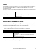
Installation Instructions XM-360 Process Module, XM-361 Temperature Module, and XM-362 Isolated Temperature Module Catalog Numbers 1440-TPR06-00RE, 1440-TUN06-00RE, 1440-TTC06-00RE 1440-xxx06-00 RE Topic Page North American Hazardous Location Approval 5 Mount the Module 6 Module Indicators 7 Reset Switch 8 Self-Test 9 Install the XM Serial Configuration Utility Software 9 Specifications 10 Additional Resources 11
XM-360 Process Module, XM-361 Temperature Module, and XM-362 Isolated Temperature Module Important User Information Read this document and the documents listed in the additional resources section about installation, configuration, and operation of this equipment before you install, configure, operate, or maintain this product. Users are required to familiarize themselves with installation and wiring instructions in addition to requirements of all applicable codes, laws, and standards.
XM-360 Process Module, XM-361 Temperature Module, and XM-362 Isolated Temperature Module Environment and Enclosure ATTENTION: This equipment is intended for use in a Pollution Degree 2 industrial environment, in overvoltage Category II applications (as defined in IEC 60664-1), at altitudes up to 2000 m (6562 ft) without derating. This equipment is not intended for use in residential environments and may not provide adequate protection to radio communication services in such environments.
XM-360 Process Module, XM-361 Temperature Module, and XM-362 Isolated Temperature Module ATTENTION: The serial communication port is intended for temporary local-programming purposes only and not intended for permanent connection. The serial cable and power connections are not to exceed 3.0 m (9.84 ft): • This product is intended to be mounted to a well-grounded mounting surface such as a metal panel or DIN rail.
XM-360 Process Module, XM-361 Temperature Module, and XM-362 Isolated Temperature Module North American Hazardous Location Approval The following information applies when operating this equipment in hazardous locations. Informations sur l’utilisation de cet équipement en environnements dangereux. Products marked "CL I, DIV 2, GP A, B, C, D" are suitable for use in Class I Division 2 Groups A, B, C, D, Hazardous Locations and nonhazardous locations only.
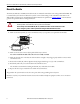
XM-360 Process Module, XM-361 Temperature Module, and XM-362 Isolated Temperature Module Mount the Module The XM® 360, XM-361, and XM-362 modules mount on a XM-944 terminal base unit, catalog number1440-TB-E. We recommend that you mount the modules after you have connected the wiring on the terminal base unit. Refer to the XM-944 Process/Temperature Terminal Base Installation Instructions, publication GMSI10-IN024, or the module user guide for the specific module for wiring information.
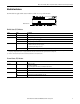
XM-360 Process Module, XM-361 Temperature Module, and XM-362 Isolated Temperature Module Module Indicators Each module has eight module status indicators, which are on top of the module. Module indicators Module Status (MS) Indicator Color State Description No color Off No power applied to the module. Green Flashing Red Module performing power-up self-test. Flashing Module operating in Program mode.(1) Solid Module operating in Run mode.
XM-360 Process Module, XM-361 Temperature Module, and XM-362 Isolated Temperature Module Channel Status Indicator (six in all) Color State Description No color Off • Normal operation with alarm limits on the channel. • No power applied to the module; look at Module Status indicator. Yellow Solid An alert level alarm condition exists on the channel (and no sensor-out-of-range or danger level alarm condition exists).
XM-360 Process Module, XM-361 Temperature Module, and XM-362 Isolated Temperature Module Self-Test The XM-360, XM-361, and XM-362 modules perform a self-test at powerup. The self-test includes a status indicator test and a device test. During the status indicator test, the indicators are turned on independently and in sequence for approximately 0.25 seconds. The device test occurs after the status indicator test. The Module Status (MS) indicator is used to indicate the status of the device self-test.
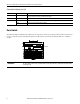
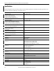
XM-360 Process Module, XM-361 Temperature Module, and XM-362 Isolated Temperature Module Specifications The following table lists the technical specifications for the XM-360, XM-361, and XM-362 modules. Specifications are the same for the three module types, except where noted.
XM-360 Process Module, XM-361 Temperature Module, and XM-362 Isolated Temperature Module Product Feature Wire type XM-36X (1) Signal connections: shielded Power connections: unshielded North American temp code T4 IEC temp code T4 (1) Use this Conductor Category information for planning conductor routing. Refer to Industrial Automation Wiring and Grounding Guidelines, publication 1770-4.1.
Rockwell Automation Support Rockwell Automation provides technical information on the Web to assist you in using its products. At http://www.rockwellautomation.com/support you can find technical and application notes, sample code, and links to software service packs. You can also visit our Support Center at https://rockwellautomation.custhelp.com/ for software updates, support chats and forums, technical information, FAQs, and to sign up for product notification updates.