
Instruction Manual

Publication GMSI10-UM005C-EN-P - May 2010
Configuration Parameters 53
Calculate and set the transducers as follows:
1. To determine the placement of Probe A, add the Cold Set Point to the
Transducer Offset, then add the Axial Position from the Active Face.
2. To determine the placement of Probe B, subtract the Cold Set Point
from the Full Scale Reading, then add the Transducer Offset and the
Axial Position from the Active Face.
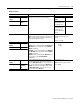
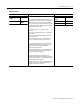
3. Enter the following data on the Channels property page in the XM-320
Position Module Configuration Tool.
1 This value is .2 volts below the lowest voltage the transducer will output for this measurement taken from the
calibration chart.
2 This value is .2 volts above the highest voltage the transducer will output for this measurement taken from the
calibration chart.
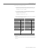
Channel 1 (Probe A) Channel 2 (Probe B)
Sensitivity 30 Sensitivity 30
Eng. Units mils Eng. Units mils
Output Data Unit mils Output Data Unit mils
Fault Low
-18
1
Fault Low
-18.2
1
Fault High
-2.6
2
Fault High
-2.8
2
DC Bias Time Constant 1 DC Bias Time Constant 1
Target Angle 90 Target Angle 90
Upscale Away Upscale Towards
Calibration Offset 250 Calibration Offset 1000
Calibration Bias Press
Calculate
Bias
Calibration Bias -33 (You
must enter
value using
formula
below)
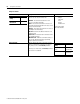
Mode Head-to-Head
Probe A Gap 250 150 0 400 mils=++=
Probe B Gap 1000 250 150 0++–900==