
Instruction Manual

Publication GMSI10-UM005C-EN-P - May 2010
24 Installing the XM-320 Position Module
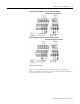
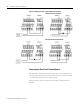
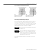
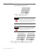
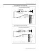
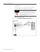
Figures 2.9 and 2.10 illustrate the behavior of the NC and NO terminals when
the relay is wired for failsafe, alarm or nonalarm condition or non-failsafe,
alarm or nonalarm condition.
IMPORTANT
T
The NC/NO terminal descriptions (page 22) correspond
to a de-energized (unpowered) relay.
When the relay is configured for non-failsafe operation, the
relay is normally de-energized.
When the relay is configured for failsafe operation, the
relay is normally energized, and the behavior of the NC and
NO terminals is inverted.
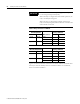
Table 2.1 Relay Connections for XM-320
Configured for
Failsafe Operation Relay 1 Terminals
Nonalarm Alarm Wire Contacts Contact 1 Contact 2
Closed Opened COM 47 50
NO 48 49
Opened Closed COM 47 50
NC 46 51
Configured for
Non-failsafe Operation Relay 1 Terminals
Nonalarm Alarm Wire Contacts Contact 1 Contact 2
Closed Opened COM 47 50
NC 46 51
Opened Closed COM 47 50
NO 48 49