XM-320 Position Module User Guide Firmware Revision 5 1440-TPS02-01RB
Important User Information Solid state equipment has operational characteristics differing from those of electromechanical equipment. Safety Guidelines for the Application, Installation and Maintenance of Solid State Controls (publication SGI-1.1 available from your local Rockwell Automation sales office or online at http://literature.rockwellautomation.com) describes some important differences between solid state equipment and hardwired electromechanical devices.
Safety Approvals The following information applies when operating this equipment in hazardous locations. Informations sur l’utilisation de cet équipement en environnements dangereux. Products marked "CL I, DIV 2, GP A, B, C, D" are suitable for use in Class I Division 2 Groups A, B, C, D, Hazardous Locations and nonhazardous locations only. Each product is supplied with markings on the rating nameplate indicating the hazardous location temperature code.
Table of Contents Chapter 1 Introduction Introducing the XM-320 Position Module . . . . . . . . . . . . . . . . . . . . . . . 1 XM-320 Module Components. . . . . . . . . . . . . . . . . . . . . . . . . . . . . . . . . 3 Using this Manual. . . . . . . . . . . . . . . . . . . . . . . . . . . . . . . . . . . . . . . . . . . 4 Organization. . . . . . . . . . . . . . . . . . . . . . . . . . . . . . . . . . . . . . . . . . . . 4 Document Conventions . . . . . . . . . . . . . . . . . . . . . . . . . . . . . . . .
Table of Contents vi Data Parameters . . . . . . . . . . . . . . . . . . . . . . . . . . . . . . . . . . . . . . . . . . . 66 Channel Data . . . . . . . . . . . . . . . . . . . . . . . . . . . . . . . . . . . . . . . . . . 66 Alarm and Relay Status . . . . . . . . . . . . . . . . . . . . . . . . . . . . . . . . . . 67 Device Mode Parameters . . . . . . . . . . . . . . . . . . . . . . . . . . . . . . . . . . . . 68 Appendix A Specifications . . . . . . . . . . . . . . . . . . . . . . . . . . . . . . . .
Table of Contents vii Discrete Input Point Object (Class ID 08H) . . . . . . . . . . . . . . . . . . . . 92 Class Attributes . . . . . . . . . . . . . . . . . . . . . . . . . . . . . . . . . . . . . . . . 92 Instance Attributes. . . . . . . . . . . . . . . . . . . . . . . . . . . . . . . . . . . . . . 93 Services . . . . . . . . . . . . . . . . . . . . . . . . . . . . . . . . . . . . . . . . . . . . . . . 93 Analog Input Point Object (Class ID 0AH) . . . . . . . . . . . . . . . . . . . . .
Table of Contents viii Publication GMSI10-UM005C-EN-P - May 2010
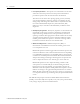
Chapter 1 Introduction This chapter provides an overview of the XM-320 Position module. It also discusses the components of the module. For information about Introducing the XM-320 Position Module See page Introducing the XM-320 Position Module 1 XM-320 Module Components 3 Using this Manual 4 The XM-320 Position module is a 2-channel general purpose monitor.
2 Introduction • Cam (Valve) Position - Valve position is a measurement of the main steam inlet valve stem position. The valve position measurement provides the operator with the current load on the machine. The amount of the steam valve opening, speed, governor, and relay valve position indication assists the operator in controlling the unit during startup and emergencies.
Introduction 3 The XM-320 also includes a single on-board relay, expandable to five, two 4-20mA outputs, and a buffered output for each input. The module can collect trend data on event, and monitor up to two alarms making it a complete position monitoring system. The module can operate stand-alone, or it can be deployed on a standard or dedicated DeviceNet network where it can provide real-time data and status information to other XM modules, PLCs, DCS, and Condition Monitoring Systems.
4 Introduction • XM-320 Position Module - Mounts on the XM-941 terminal base unit via a keyswitch and a 96-connector. The XM-320 contains the measurement electronics, processor, relay, and serial interface port for local configuration. IMPORTANT The XM-441 Expansion Relay module may be connected to the XM-320 module via the XM-941 terminal base unit. When connected to the XM-320, the Expansion Relay module simply “expands” the capability of the XM-320 by adding four additional epoxy-sealed relays.
Introduction 5 Document Conventions There are several document conventions used in this manual, including the following: The XM-320 Position Module is referred to as XM-320, Position module, module, or device throughout this manual. TIP EXAMPLE A tip indicates additional information which may be helpful. This convention presents an example.
6 Introduction Publication GMSI10-UM005C-EN-P - May 2010
Chapter 2 Installing the XM-320 Position Module This chapter discusses how to install and wire the XM-320 Position Module. It also describes the module indicators and the basic operations of the module.
8 Installing the XM-320 Position Module XM Installation Requirements This section describes wire, power and grounding requirements, and instructions for an XM system. Wiring Requirements Use solid or stranded wire. All wiring should meet the following specifications: • 14 to 22 AWG copper conductors without pretreatment; 8 AWG required for grounding the DIN rail for electromagnetic interference (emi) purposes • Recommended strip length 8 millimeters (0.
Installing the XM-320 Position Module 9 Figure 2.
10 Installing the XM-320 Position Module IMPORTANT See Application Technique "XM Power Supply Solutions", publication ICM-AP005A-EN-E, for guidance in architecting power supplies for XM systems. Grounding Requirements Use these grounding requirements to ensure safe electrical operating circumstances, and to help avoid potential emi and ground noise that can cause unfavorable operating conditions for your XM system. DIN Rail Grounding The XM modules make a chassis ground connection through the DIN rail.
Installing the XM-320 Position Module 11 Figure 2.
12 Installing the XM-320 Position Module Figure 2.3 DIN Rail Grounding Block Panel/Wall Mount Grounding The XM modules can also be mounted to a conductive mounting plate that is grounded. See Figure 2.5. Use the grounding screw hole provided on the terminal base to connect the mounting plate the Chassis terminals. Figure 2.
Installing the XM-320 Position Module 13 Figure 2.5 Panel/Wall Mount Grounding 1 Power Supply 1 Power Supply 1 Use 14 AWG wire.
14 Installing the XM-320 Position Module 24V Common Grounding 24V power to the XM modules must be grounded. When two or more power supplies power the XM system, ground the 24V Commons at a single point, such as the ground bus bar. IMPORTANT IMPORTANT If it is not possible or practical to ground the -24Vdc supply, then it is possible for the system to be installed and operate ungrounded.
Installing the XM-320 Position Module 15 Figure 2.6 Grounded DeviceNet V- at XM Module To Ground Bus ATTENTION Use of a separate DeviceNet power supply is not permitted. See Application Technique "XM Power Supply Solutions", publication ICM-AP005A-EN-E, for guidance in using XM with other DeviceNet products. For more information on the DeviceNet installation, refer to the ODVA Planning and Installation Manual - DeviceNet Cable System, which is available on the ODVA web site (http://www.odva.org).
16 Installing the XM-320 Position Module The terminal base can be DIN rail or wall/panel mounted. Refer to the specific method of mounting below. ATTENTION The XM modules make a chassis ground connection through the DIN rail. Use zinc plated, yellow chromated steel DIN rail to assure proper grounding. Using other DIN rail materials (e.g. aluminum, plastic, etc.), which can corrode, oxidize or are poor conductors can result in improper or intermittent platform grounding.
Installing the XM-320 Position Module 17 3. Rotate the terminal base onto the DIN rail with the top of the rail hooked under the lip on the rear of the terminal base. 4. Press down on the terminal base unit to lock the terminal base on the DIN rail. If the terminal base does not lock into place, use a screwdriver or similar device to open the locking tab, press down on the terminal base until flush with the DIN rail and release the locking tab to lock the base in place.
18 Installing the XM-320 Position Module 5. Gently push the side connector into the side of the neighboring terminal base unit to complete the backplane connection. Panel/Wall Mounting Installation on a wall or panel consists of: • laying out the drilling points on the wall or panel • drilling the pilot holes for the mounting screws • installing the terminal base units and securing them to the wall or panel Use the following steps to install the terminal base on a wall or panel.
Installing the XM-320 Position Module 19 1. Lay out the required points on the wall/panel as shown in the drilling dimension drawing below. Side Connector 2. Drill the necessary holes for the #6 self-tapping mounting screws. 3. Secure the terminal base unit using two #6 self-tapping screws. 4. To install another terminal base unit, retract the side connector into the base unit. Make sure it is fully retracted. 5. Position the terminal base unit up tight against the neighboring terminal base.
20 Installing the XM-320 Position Module Figure 2.7 XM-941 Terminal Base Unit XM-941, Cat. No. 1440-TB-B Terminal Block Assignments The terminal block assignments and descriptions for the XM-320 module are shown below. ATTENTION WARNING The terminal block assignments are different for different XM modules. The following table applies only to the XM-320. Refer to the installation instructions for the specific XM module for its terminal assignments.
Installing the XM-320 Position Module 21 Terminal Block Assignments No.
22 Installing the XM-320 Position Module Terminal Block Assignments No.
Installing the XM-320 Position Module IMPORTANT IMPORTANT ATTENTION 23 A Class 2 circuit can be provided by use of an NEC Class 2 rated power supply, or by using a SELV or PELV rated power supply with a 5 Amp current limiting fuse installed before the XM module(s). 24Vdc needs to be wired to terminal 44 (+24 V In) to provide power to the device and other XM modules linked to the wired terminal base via the side connector. The power connections are different for different XM modules.
24 Installing the XM-320 Position Module IMPORTANT T The NC/NO terminal descriptions (page 22) correspond to a de-energized (unpowered) relay. When the relay is configured for non-failsafe operation, the relay is normally de-energized. When the relay is configured for failsafe operation, the relay is normally energized, and the behavior of the NC and NO terminals is inverted. Table 2.
Installing the XM-320 Position Module 25 Figure 2.9 Relay Connection - Failsafe, Nonalarm Condition Non-failsafe, Alarm Condition Figure 2.10 Relay Connection - Failsafe, Alarm Condition Non-failsafe, Nonalarm Condition Alternate Relay Wiring Figures 2.11 and 2.12 show how to wire both ends of a single external indicator to the XM terminal base for failsafe, nonalarm or alarm condition, or non-failsafe, nonalarm or alarm condition.
26 Installing the XM-320 Position Module Figure 2.11 Relay Connection - Failsafe, Nonalarm Condition Non-failsafe, Alarm Condition Figure 2.12 Relay Connection - Failsafe, Alarm Condition Non-failsafe, Nonalarm Condition Connecting the Short Circuit Protected Output The XM-320 provides short circuit protected outputs of all transducer input signals. The protected output connections may be used to connect the module to portable data collectors or other online systems. Figure 2.
Installing the XM-320 Position Module 27 Figure 2.13 Short Circuit Protected Output Connections Connecting the Remote Relay Reset Signal If you set the module relay to latching and the relay activates, the relay stays activated even when the condition that caused the alarm has ended. The remote relay reset signal enables you to reset your module relay remotely after you have corrected the alarm condition. This includes latched relays in the Expansion Relay module when it is attached to the XM-320.
28 Installing the XM-320 Position Module Figure 2.14 Remote Relay Reset Signal Connection ATTENTION The Switch Input circuits are functionally isolated from other circuits. It is recommended that the Switch RTN signal be grounded at a signal point. Connect the Switch RTN signal to the XM terminal base (Chassis terminal) or directly to the DIN rail, or ground the signal at the switch or other equipment that is wired to the switch.
Installing the XM-320 Position Module 29 Connecting the Setpoint Multiplication Switch You can configure the module to multiply the alarm setpoints, or inhibit the alarms during the start-up period. This can be used to avoid alarm conditions that may occur during startup, for example, when the monitored machine passes through a critical speed. Wire the Setpoint Multiplication switch to the terminal base unit as shown in Figure 2.16. Figure 2.
30 Installing the XM-320 Position Module Figure 2.17 4-20mA Output Connections ATTENTION The 4-20mA outputs are functionally isolated from other circuits. It is recommended that the outputs be grounded at a single point. Connect the 4-20mA (-) to the XM terminal base (Chassis terminal) or directly to the DIN rail, or ground the signal at the other equipment in the 4-20mA loop.
Installing the XM-320 Position Module 31 Figure 2.18 Non-contact sensor to channel 1 wiring TYPICAL WIRING FOR NON-CONTACT SENSOR TO XM-320 POSITION MODULE CHANNEL 1 Isolated Sensor Driver Shield Floating -24 SIG COM Signal Common Channel 1 Input Signal 16 0 Shield 37 -24V DC 22 6 43 Figure 2.
32 Installing the XM-320 Position Module Connecting an LVDT The following figures show the wiring from a linear variable differential transformer (LVDT) to the terminal base unit of the XM-320. ATTENTION You may ground the cable shield at either end of the cable. Do not ground the shield at both ends. Recommended practice is to ground the cable shield at the XM-320 terminal base and not at the transducer. Any convenient Chassis terminal may be used (see Terminal Block Assignments on page 20). Figure 2.
Installing the XM-320 Position Module 33 Figure 2.21 LVDT to channel 2 wiring TYPICAL WIRING FOR LINEAR VARIABLE DIFFERENTIAL TRANSFORMER (LVDT) TO XM-320 POSITION MODULE CHANNEL 2 Cable shield not connected at this end Signal Ground Input Signal Power Ground Signal Ground Channel 2 Input Signal Shield Power Ground +24V DC 17 1 38 22 6 43 +24V DC Connecting a Cam Potentiometer The following figures show the wiring from a cam potentiometer to the terminal base unit of the XM-320.
34 Installing the XM-320 Position Module Figure 2.22 Cam potentiometer to channel 1 wiring TYPICAL WIRING FOR CAM (VALVE) POTENTIOMETER TO XM-320 POSITION MODULE CHANNEL 1 Cable shield not connected at this end Signal Common Channel 1 Input Signal +24V DC Signal Common Shield 16 0 37 22 +24V DC 6 Channel 1 Input Signal 28 Figure 2.
Installing the XM-320 Position Module 35 Connecting a Non-contact Sensor and an LVDT The figure below shows the wiring of a non-contact sensor to channel 1 and an LVDT to channel 2 of the XM-320. ATTENTION IMPORTANT You may ground the cable shield at either end of the cable. Do not ground the shield at both ends. Recommended practice is to ground the cable shield at the XM-320 terminal base and not at the transducer.
36 Installing the XM-320 Position Module Figure 2.
Installing the XM-320 Position Module 37 The DB-9 connector should be wired to the terminal base unit as follows. XM-320 Terminal Base Unit (Cat. No. 1440-TB-B) DB-9 Female Connector TX Terminal (terminal 7) ---------------------- Pin 2 (RD - receive data) RX Terminal (terminal 8) ---------------------- Pin 3 (TD - transmit data) RTN Terminal (terminal 9) --------------------- Pin 5 (SG - signal ground) • Mini-Connector - The mini-connector is located on the top of the XM-320, as shown below.
38 Installing the XM-320 Position Module DeviceNet Connection The XM-320 includes a DeviceNet™ connection that allows the module to communicate directly with a programmable controller, distributed control system (DCS), or another XM module. DeviceNet is an open, global, industry-standard communications network designed to provide an interface through a single cable from a programmable controller to a smart device such as the XM-320 module.
Installing the XM-320 Position Module ATTENTION IMPORTANT 39 The DNet V+ and DNet V- terminals are inputs to the XM module. Do not attempt to pass DeviceNet power through the XM terminal base to other non-XM equipment by connecting to these terminals. Failure to comply may result in damage to the XM terminal base and/or other equipment.
40 Installing the XM-320 Position Module WARNING IMPORTANT When you insert or remove the module while power is on, an electrical arc can occur. This could cause an explosion in hazardous location installations. Be sure that power is removed or the area is nonhazardous before proceeding. Install the overlay slide label to protect serial connector and electronics when the serial port is not in use. 1.
Installing the XM-320 Position Module Module Indicators 41 The XM-320 has six LED indicators, which include a module status (MS) indicator, a network status (NS) indicator, a status indicator for each channel (CH1 and CH2), an activation indicator for the Setpoint Multiplier, and a status indicator for the Relay. The LED indicators are located on top of the module. Figure 2.
42 Installing the XM-320 Position Module Network Status (NS) Indicator Color State Description No color Off Module is not online. • Module is autobauding. • No power is applied to the module, look at Module Status LED. Green Red 1 Flashing Module is online (DeviceNet) but no connections are currently established.1 Solid Module is online with connections currently established. Flashing One or more I/O connections are in the timed-out state.
Installing the XM-320 Position Module Basic Operations 43 Powering Up the Module The XM-320 performs a self-test at power-up. The self-test includes an LED test and a device test. During the LED test, the indicators will be turned on independently and in sequence for approximately 0.25 seconds. The device test occurs after the LED test. The Module Status (MS) indicator is used to indicate the status of the device self-test.
44 Installing the XM-320 Position Module The switch can be used to reset all latched relays in the module. This includes the relays in the Expansion Relay Module when it is connected to the XM-320. IMPORTANT Publication GMSI10-UM005C-EN-P - May 2010 The Reset switch resets the relays only if the input is no longer in alarm or the condition that caused the alarm is no longer present.
Chapter 3 Configuration Parameters This chapter provides a complete listing and description of the XM-320 parameters. The parameters can be viewed and edited using the XM Serial Configuration Utility software and a personal computer. If the module is installed on a DeviceNet network, configuring can also be performed using a network configuration tool such as RSNetWorx (Version 3.0 or later). Refer to your configuration tool documentation for instructions on configuring a device.
46 Configuration Parameters Channel Parameters The Channel parameters define the characteristics of the transducers you will be using with the XM-320. Use the parameters to configure the transducer sensitivity, operating range, power requirements, measurement mode, and calibration offset. There are two instances of the parameters, one for each channel. TIP The Channel LED will flash red when a transducer fault condition exists on a channel even if you are not using the channel.
Configuration Parameters 47 Channel Parameters Parameter Name Description Values/Comments DC Bias Time Constant The time constant used for exponential averaging Seconds (low pass filtering) of the transducer DC bias measurement. The corner frequency for the low pass filter is 1 / (2π x DC Bias Time Constant). The greater the value entered, the longer the settling time of the measured value to a change in the input signal. See example table below.
48 Configuration Parameters Channel Parameters Parameter Name Description Values/Comments Calibration Bias Sets the zero or green position. The zero position is the normal operating position. Setting the zero position compensates for the static gap. This allows the module to display only the displacement around the zero position. Volts Use one of the formulas below to calculate the Calibration Bias.
Configuration Parameters Measurement Mode Parameter 49 The Measurement Mode parameter controls how the two axial sensors are used to calculate the position measurement. Use this parameter to configure the mode of operation. Measurement Mode Parameter Name XM Configuration Utility EDS File Mode Measurement Mode Description Values/Comments Select the mode of the two axial sensors.
50 Configuration Parameters Figure 3.1 Normal Mode NORMAL MODE (straight targets) (angled targets) (mixed targets) The XM-320 provides monitoring facilities for the following machine measurements when in normal mode. • • • • Axial (thrust) Position Differential Expansion Case Expansion Valve Position IMPORTANT Publication GMSI10-UM005C-EN-P - May 2010 For the valve position measurement, Sensitivity must be set to "deg.
Configuration Parameters 51 Head-To-Head Mode The head-to-head mode allows extended range operation by using two probes in a “back to back” arrangement shown in the illustration in Figure 3.2. This mode can be used when the machine does not have enough space for larger diameter probes. It is not necessary for the scales to be symmetrical in this mode, and probes of different voltage sensitivities can be used within the one module. Figure 3.
52 Configuration Parameters Figure 3.3 Head-to-Head Mode Note: The direction of differential growth for an upscale reading is away from Probe A and towards Probe B. The chart below shows gap-to-instrument reading-to-voltage outputs for typical 500 mil transducers with an offset of 150 mils. Note that the offset gap of a transducer is the gap closest to the transducer where the transducer’s response to gap change becomes non-linear and not useful for measurement.
Configuration Parameters 53 Calculate and set the transducers as follows: 1. To determine the placement of Probe A, add the Cold Set Point to the Transducer Offset, then add the Axial Position from the Active Face. Probe A Gap = 250 + 150 + 0 = 400 mils 2. To determine the placement of Probe B, subtract the Cold Set Point from the Full Scale Reading, then add the Transducer Offset and the Axial Position from the Active Face. Probe B Gap = 1000 – 250 + 150 + 0 = 900 3.
54 Configuration Parameters Calibration Bias Calculation Since Probe B is gapped beyond the operating range, you must manually calculate the calibration bias as well as the transducer DC bias. 1. To determine the Transducer DC Bias, subtract Position B Gap from Transducer Offset, multiply by the Sensitivity and then add the Transducer Offset voltage. Transducer DC Bias = 0.03 × ( 150 – 900 ) – 3 = -25.5 2.
Configuration Parameters 55 Figure 3.4 Radial Cancel Mode RADIAL CANCEL MODE (two angles) radial movement axial movement (one angle) The XM-320 provides monitoring facilities for the following machine measurements when in radial cancel mode. • Standard Single Ramp Differential Expansion • Non-standard Single Ramp Differential Expansion • Dual Ramp Differential Expansion TIP Alarm Parameters In radial cancel mode, all position measurements are stored in channel 1.
56 Configuration Parameters Alarm Parameters Parameter Name Description Values/Comments Condition Controls when the alarm should trigger. Options: Greater Than Less Than Inside Range Outside Range • Greater than - Triggers the alarm when the measurement value is greater than or equal to the Alert and Danger Threshold values. The Danger Threshold value must be greater than or equal to the Alert Threshold value for the trigger to occur.
Configuration Parameters 57 Alarm Parameters Parameter Name Description Values/Comments Hysteresis The amount that the measurement value must fall (below the threshold) before the alarm condition is cleared. For example, Alert Threshold = 120 and Hysteresis = 2. The alarm (alert) activates when the measured value is 120 and will not clear until the measured value is 118. Same measurement unit as Output Data Unit selection for the specified channel.
58 Configuration Parameters Relay Parameters The Relay parameters control the operation of the on-board relay, as well as the relays on the Expansion Relay (XM-441) module. Use these parameters to configure which alarm(s) the relay is associated with as well as the behavior of the relay. IMPORTANT A relay can be defined, regardless of whether or not it is physically present. A non-physical relay is a virtual relay.
Configuration Parameters 59 Relay Parameters Parameter Name Description XM Configuration EDS File Utility Latching Latching Option XM Configuration EDS File Utility Logic XM Configuration EDS File Utility Alarm A/B XM Configuration Utility EDS File Check means latching (relay must be explicitly reset) Latching Clear means non-latching (relay is reset once the alarm condition has passed Nonlatching Enter a value from 0 to 25.
60 Configuration Parameters Relay Parameters Parameter Name XM Configuration EDS File Utility Alarm Status to Activate On Description Values/Comments Sets the alarm conditions that will cause the relay to activate. You can select more than one. Options: Normal Danger Xdcr Fault Alert Disarm Module Fault Alarm Levels • Normal - The current measurement is not in excess of any alarm thresholds.
Configuration Parameters 61 Relay Parameters Parameter Name Description XM Configuration EDS File Utility Failsafe Relay Failsafe Option Values/Comments Controls whether the relay is failsafe or nonfail-safe. Failsafe operation means that when in alarm, the relay contacts are in their "normal," de-energized, or "shelf-state" positions. In other words, normally closed relays are closed in alarm, and normally open relays are open in alarm. With failsafe operation, a power failure equals an alarm.
62 Configuration Parameters 4-20mA Output Parameters The 4-20mA output parameters define the characteristics of the two 4-20mA output signals. The parameters are the same for each output. 4-20mA Parameters Parameter Name Description Values/Comments Enable Enables/disables the 4-20 mA output. Min Range The measured value associated with the 4 mA. Max Range The measured value associated with the 20 mA.
Configuration Parameters Triggered Trend Parameters 63 The XM-320 can collect a triggered trend. A triggered trend is a time-based trend that is collected when a relay on the XM-320 is activated, or the module receives a trigger event. Once the triggered trend is configured, the XM-320 continuously monitors the trended measurements. When a trigger occurs, the XM-320 collects additional data as specified by the Post Trigger parameter. The XM-320 can only store one triggered trend.
64 Configuration Parameters Triggered Trend Parameters Parameter Name Description Values/Comments Relay Number Sets the relay that triggers the trend to be collected. None means that the trend can only be triggered manually or by a trigger event (for example, XM-440). Relay Number 1 is the on-board relay. Numbers 2 through 5 are either relays on the Expansion Relay module when it’s connected to the module or virtual relays. Note: The relay must be enabled. Refer to Relay Parameters on page 58.
Configuration Parameters I/O Data Parameters 65 The I/O data parameters are used to configure the content and size of the DeviceNet I/O Poll response message. IMPORTANT The XM module must be free of Poll connections when configuring the Poll Output (Poll Response Assembly) and Poll Size. Any attempt to download the parameters while a master device has established the Poll connection with the XM module will result in an error.
66 Configuration Parameters The Data parameters are used to view the measured values of the input channels and the 4–20mA outputs, as well as to monitor the status of the channels, alarms, and relays. Data Parameters TIP To view all the data parameters in the XM Serial Configuration Utility, click the View Data tab. Channel Data Channel Data Parameters Parameter Name Description Channel Status States whether a fault condition exists. If a fault exists, the measurement value may not be accurate.
Configuration Parameters 67 Alarm and Relay Status Alarm and Relay Status Parameters Parameter Name Description Values/Comments Alarm Status States the current status of the alarm. Possible status values. • Normal - The alarm is enabled, the device is in Run mode, there is no transducer fault, and the current measurement is not within the Alert or Danger Threshold value(s).
68 Configuration Parameters Device Mode Parameters The Device Mode parameters are used to control the functions and the behavior of the device. IMPORTANT The XM Serial Configuration Utility handles these parameters automatically and transparently to the user. Device Mode Parameters Parameter Name Description Values/Comments Device Mode Sets the current operation mode of the device. Refer to Changing Operation Modes on page 73 for more information.
Appendix A Specifications Appendix A lists the technical specifications for the XM-320 Position Module. XM-320 Technical Specifications Product Feature Specification Communications DeviceNet Standard DeviceNet protocol for all functions NOTE: The XM-320 uses only the DeviceNet protocol, not power. Module power is provided independently.
70 Specifications XM-320 Technical Specifications Product Feature Specification Outputs 4-20mA Outputs Two isolated outputs 600 ohm max load Buffered Outputs 2 outputs; 1 per channel Indicators 6 LEDs Module Status - red/green Network Status - red/green Channel 1 Status - yellow/red Channel 2 Status - yellow/red Setpoint Multiplier - yellow Relay - red Measurement Modes Normal (two independent channels) Head-to-head Radial cancel Delta Time Buffer Number of Records 2048 Delta Time Interval 1 to 3600 s
Specifications 71 XM-320 Technical Specifications Product Feature Specification On-board Relay Rating Maximum Voltage: 125V dc, 125V ac Maximum Current: 3.5A* Minimum Current: 0 Maximum Power: 60W, 62.5VA *Max current is up to 40°C, then derates to 2A at 65°C. Agency Rating: 120V ac @ 0.5A 110V dc @ 0.3A 30V dc @ 1.0A Failsafe Normally energized (failsafe), or Normally de-energized (non-fail-safe) Latching Latching, or Non-latching Time Delay 0 to 25.
72 Specifications XM-320 Technical Specifications Product Feature Specification Heat Production Maximum: 5.28 Watts (18 BTU/hr) Typical: 3.96 Watts (13.5 BTU/hr) Transducer Isolated 24V dc, user configurable with wiring Environmental Operating Temperature -20 to +65°C (-4 to +149°F) Storage Temperature -40 to +85°C (-40 to +185°F) Relative Humidity 95% non-condensing All printed circuit boards are conformally coated in accordance with IPC-A-610C. Physical Dimensions Height: 3.8in (97mm) Width: 3.
Appendix B DeviceNet Information Electronic Data Sheets Electronic Data Sheet (EDS) files are simple text files used by network configuration tools such as RSNetWorx (Version 3.0 or later) to help you identify products and easily commission them on a network. The EDS files describe a product’s device type, product revision, and configurable parameters on a DeviceNet network. The EDS files for the XM modules are installed on your computer with the XM configuration software.
74 DeviceNet Information Transition to Program Mode Parameter values can only be downloaded to an XM module while the module is in Program mode. Any attempt to download a parameter value while the module is in Run mode will result in a Device State Conflict error. To transition an XM module from Run mode to Program mode on a DeviceNet network, set the Device Mode parameter to "Program mode" and click Apply.
DeviceNet Information 75 The table below defines the services supported by the XM modules. The table includes the service codes, classes, instances, and attributes by their appropriate hexadecimal codes. Use the Class Instance Editor in RSNetWorx to execute these services, as illustrated in the example below.
76 DeviceNet Information Example To save the configuration parameters to the non-volatile memory (EEPROM), fill in the Class Instance Editor as shown below. Clear Send the attribute ID and then enter the Class (320 hex) and Instance (1) Select the Save service code Click Execute to initiate the action Invalid Configuration Errors A Start or Save service request to an XM module may return an Invalid Device Configuration error when there is a conflict amongst the configuration settings.
DeviceNet Information 77 Additional Error Codes returned with the Invalid Device Configuration Error (0xD0) XM-320 I/O Message Formats Error Code (Hex) Description 0A Too many alarms associated with a single measurement. 0B Invalid node address in the alarm list. 0C Too many alarms in the alarm list. Or, no alarms in the alarm list. 0D Alarm levels cannot be zero for alarms that are enabled. 0E Too many slaves in the scanner’s input data table.
78 DeviceNet Information The Poll response data can also be requested explicitly through Assembly Object (Class ID 0x4), Instance 101 (0x65), Data Attribute (3). The following table shows the static data format of Assembly instance 101. XM-320 I/O Poll Response Message Format Byte Definition 0–3 Channel 1 Position measurement value 4–7 Channel 2 Position measurement value COS Message Format The XM-320 COS message contains five bytes of data as defined in the table below.
DeviceNet Information 79 Alarm Status Descriptions Alarm Status Value Description 5 Module Fault 6 Tachometer Fault 7 Reserved Setpoint Multiplier Status Descriptions Setpoint Multiplier Status Value Description 0 Not Activated 1 Activated Relay Status Descriptions Relay Status Value Description 0 Not Activated 1 Activated Bit-Strobe Message Format The Bit-Strobe command sends one bit of output data to each XM slave whose node address appears in the master’s scanlist.
80 DeviceNet Information The XM modules use the bit received in a Bit-Strobe connection as a trigger event. When the bit number corresponding to the XM module’s node address is set, the XM module will collect the triggered trend data. Note that the XM modules do not send data in the Bit-Strobe response. ADR for XM Modules Automatic Device Replacement (ADR) is a feature of an Allen-Bradley DeviceNet scanner.
DeviceNet Information 81 • An XM module will enter Run mode automatically after the ADR scanner restores the module’s configuration only if the module is in Run mode at the time the configuration is saved to the scanner. If the module is in Program mode when the configuration is saved, then the module will remain in Program after the configuration is downloaded by the ADR scanner. • The ADR scanner saves and restores only the configuration parameters contained in the module’s EDS file.
82 DeviceNet Information Publication GMSI10-UM005C-EN-P - May 2010
Appendix C DeviceNet Objects Appendix C provides information on the DeviceNet objects supported by the XM-320 module.
84 DeviceNet Objects The Identity Object provides identification and general information about the device. Identity Object (Class ID 01H) Class Attributes The Identity Object provides no class attributes. Instance Attributes Table C.
DeviceNet Objects 85 Table C.2 Identity Object Status Bit Name Description 4 Boot Program Vendor-specific, indicates that the boot program is running. The Main Application must be corrupt or missing. 5-7 Vendor-specific, not implemented 8 Minor Recoverable Fault 9 Minor Unrecoverable Not implemented Fault 10 Major Recoverable Fault 11 Major Unrecoverable Set when there is a module status fault (Module Status Fault LED is solid red).
86 DeviceNet Objects Class Attributes Table C.4 DeviceNet Object Class Attributes Attr ID Access Rule Name Data Type Default Value 1 Get Revision UINT 2 Instance Attributes Table C.
DeviceNet Objects 87 Services Table C.6 DeviceNet Object Services Service Code Class/Instance Usage Name 0Eh Class/Instance Get_Attribute_Single 10h Instance Set_Attribute_Single1 4Bh Instance Allocate_Master/Slave_Connetion_Set 4Ch Instance Release_Group_2_Identifier_Set 1 Attributes can only be set while the device is in Program Mode. See the description of the Device Mode Object for more information.
88 DeviceNet Objects Instance Attributes Table C.9 Assembly Object Instance Attributes Attr ID Access Rule Name Data Type Value 1 Get Number of Members in list UINT Only supported for Dynamic Assembly instance 2 Set Member List Array of STRUCT: Only supported for Dynamic Assembly instance Member Data Description 3 Get UINT Size of member data value in bits Member Path Size UINT Member Path Packed EPATH Data Defined in tables on the following pages.
DeviceNet Objects 89 Instance 101 - Measurement Values This is the default assembly instance that is sent using the I/O Poll Response message when an I/O Poll Request is received from a DeviceNet Master. Table C.
90 DeviceNet Objects Table C.
DeviceNet Objects 91 Instances Table C.14 Connection Object Instances Instance Description 1 Explicit Message Connection for pre-defined connection set 2 I/O Poll Connection 3 I/O Strobe Connection 4 I/O COS (change of state) Connection 11 - 17 Explicit Message Connection Instance Attributes Table C.15 Connection Object Instance Attributes Attr ID Access Rule Name Data Type Description 1 Get State USINT State of the object.
92 DeviceNet Objects Table C.15 Connection Object Instance Attributes Attr ID Access Rule 15 Name Data Type Description Get Consumed Connection Path Length UINT Number of bytes in the consumed_connection_path attribute. 16 Get Consumed Connection Path Array of USINT Specifies the Application Object(s) that are to receive the data consumed by this Connection Object. See DeviceNet Specification Volume 1 Appendix I.
DeviceNet Objects 93 Instance Attributes Table C.18 Discrete Input Object Instance Attributes Attr ID Access Rule Name Data Type Description Semantics 3 Get Value BOOL Setpoint Multiplier 0 = Off 1 = On 199 Set Backdoor Service USINT Setting this attribute is equivalent to requesting the specified service. Set to one of the following values to perform the specified service: 0x32 = Open 0x33 = Close Services Table C.
94 DeviceNet Objects Instances Table C.21 Analog Input Point Object Instances Instance Name Description 1 Position Position measurement for transducer 1. 2 Position Position measurement for transducer 2. Instance Attributes Table C.22 Analog Input Point Object Class Attributes Attr ID Access Rule Name Data Type Description Semantics 3 Get Value REAL The position measurement value. The raw measured value plus any offset specified by Calibration Bias.
DeviceNet Objects Parameter Object (Class ID 0FH) 95 The Parameter Object provides the interface to the XM-320 configuration data. There are 15 Parameter Object instances implemented in the XM-320 module. Parameter Object instances 1-4 and 6-15 are implemented to provide an alternate method of setting the configuration parameters with EPATH or ENGUNIT data types. Instance 5 of the Parameter Object is for setting the device "Mode.
96 DeviceNet Objects Instances There are 15 instances of this object. Table C.
DeviceNet Objects 97 Table C.25 Parameter Object Instances Instance Read Only 16 17 Name Data Type Valid Values Default Value No Poll Connection Produced Connection Path USINT 101, 199 (Assembly Object instance number) 101 No Poll Connection Produced Connection Size UINT 4 - 124 8 Instance Attributes Table C.
98 DeviceNet Objects Services Table C.27 Parameter Object Services Service Code Class/Instance Usage Name Description 0Eh Class/Instance Get_Attribute_Single Returns the contents of the specified attribute. 10h Class Set_Attribute_Single Sets the contents of the specified attribute.1 1 Attributes can only be set while the device is in Program Mode. See the description of the Device Mode Object for more information.
DeviceNet Objects 99 Services Table C.29 Acknowledge Handler Object Services Service Code Class/Instance Usage Name 0Eh Instance Get_Attribute_Single 10h Instance Set_Attribute_Single The Alarm Object models a two-stage (alert and danger levels) alarm. Alarm Object (Class ID 31DH) Class Attributes Table C.30 Alarm Object Class Attributes Attr ID Access Rule Name Data Type Description Semantics 1 Get Revision USINT Revision of the implemented object.
100 DeviceNet Objects Table C.31 Alarm Object Instance Attributes Attr ID Access Rule Name Data Type Description Semantics 6 Get Threshold Units USINT Indicates whether the threshold and hysteresis value are specified in units of measure. Set to 1 1 = Measurement units 7 Get/Set Condition USINT Indicates on which side of the threshold values the alarm and danger conditions exist.
DeviceNet Objects 101 Services Table C.32 Alarm Object Services Service Code Class/Instance Usage Name Description 0Eh Instance Get_Attribute_Single Returns a single attribute. 10h Instance Set_Attribute_Single Sets a single attribute.1 1 Device Mode Object (Class ID 320H) Attributes can only be set while the device is in Program Mode. See the description of the Device Mode Object for more information.
102 DeviceNet Objects Services Table C.34 Device Mode Object Services Service Code Class/Instance Usage Name Description 0Eh Instance Get_Attribute_Single Return the value of a single attribute. 10h Instance Set_Attribute_Single Set the value of a single attribute. 07h Instance Stop Transitions from Run to the Program state. 06h Instance Start Validate the device configuration settings and transition to the Run state if OK. 05h Instance Reset Transition to the Power Up state.
DeviceNet Objects 103 Class Attributes Table C.35 Relay Object Class Attributes Attr ID Access Rule 3 100 Name Data Type Description Semantics Get Number of Instances UINT Number of Instances in this class. 5 Set Reset All USINT Setting this attribute is equivalent to executing the Class Reset service Reset All is an attribute that provides a way to perform a Class level Reset service via the Set_Attribute_Single service.
104 DeviceNet Objects Table C.36 Relay Object Instance Attributes Attr ID Access Rule Name Data Type Description Semantics 9 Get/Set Alarm Level BYTE Specifies what alarm status values will cause the relay to activate. 0 = Normal 1 = Alert 2 = Danger 3 = Disarm 4 = Xdcr Fault 5 = Module Fault 10 Get/Set Alarm Identifier A EPATH Identifies the first alarm status the relay monitors. See Parameter Object instances 6 to 10.
DeviceNet Objects Transducer Object (Class ID 328H) 105 The Transducer Object models a transducer. Class Attributes The Transducer Object provides no class attributes. Instances There are 2 instances of this object. Instance Attributes Table C.38 Transducer Object Instance Attributes Attr ID Access Rule Name Data Type Description 3 Get DC Bias REAL The measured average DC Volts bias of the transducer signal in volts.
106 DeviceNet Objects Table C.38 Transducer Object Instance Attributes Attr ID Access Rule Name Data Type Description Semantics 11 Get/Set Target Angle REAL The angle of the target relative to the shaft in degrees. 0 to 90 degrees 12 Get/Set Upscale BOOL Indicates the movement of the target relative to the transducer which is considered positive displacement.
DeviceNet Objects 107 Instances There are 2 instances of this object. Instance Attributes Table C.40 4-20mA Output Object Instance Attributes Attr ID Access Rule Name Data Type Description Semantics 3 Get/Set Value REAL The current output value. mA 4 Get/Set Enable BOOL Indicates whether this 4-20mA output is enabled. 0 = Disabled 1 = Enabled 5 Get/Set Max Range REAL The measured value associated with 20mA. 6 Get/Set Min Range REAL The measured value associated with 4mA.
108 DeviceNet Objects Publication GMSI10-UM005C-EN-P - May 2010
Glossary alarm An alarm alerts you to a change in a measurement. For example, an alarm can notify you when the measured vibration level for a machine exceeds a pre-defined value. Automatic Device Replacement (ADR) A means for replacing a malfunctioning device with a new unit, and having the device configuration data set automatically. The ADR scanner uploads and stores a device’s configuration.
Glossary 110 Change of State (COS) DeviceNet communications method in which the XM module sends data based on detection of any changed value within the input data (alarm or relay status). current configuration The current configuration is the most recently loaded set of configuration parameters in the XM module’s memory. When power is cycled, the current configuration is loaded with either the saved configuration (in EEPROM) or the factory defaults (if there is no saved configuration).
Glossary 111 Help window A window that contains help topics that describe the operation of a program. These topics may include: • • • • An explanation of a command. A description of the controls in a dialog box or property page. Instructions for a task. Definition of a term. MAC ID See node address. master device A device which controls one or more slave devices. The XM-440 Master Relay module is a master device. node address A DeviceNet network can have as many as 64 devices connected to it.
Glossary 112 Program mode The XM module is idle. Typically this occurs when the module configuration settings are being updated with the XM Configuration program. In Program mode, the signal processing/measurement process is stopped, and the status of the alarms is set to the disarm state to prevent a false alert or danger status. Run mode In Run mode, the module collects measurement data and monitors each measurement device.
Glossary 113 virtual relay A virtual relay is a non-physical relay. It has the same capabilities (monitor alarms, activation delay, change status) as a physical relay only without any physical or electrical output. The virtual relay provides additional relay status inputs to a controller, PLC, or an XM-440 Master Relay module (firmware revision 5.0 and later). XM configuration XM configuration is a collection of user-defined parameters for XM modules.
Glossary 114 Publication GMSI10-UM005C-EN-P - May 2010
Index Numerics 24V common grounding requirements 14 4-20mA Output Object 106 4-20mA output parameters 62 Enable 62 Max Range 62 Min Range 62 4-20mA outputs, wiring 29 A Acknowledge Handler Object 98 Alarm Object 99 alarm parameters 55 Alert Threshold (High) 56 Alert Threshold (Low) 56 Condition 56 Danger Threshold (High) 56 Danger Threshold (Low) 56 Enable 55 Hysteresis 57 Name 55 Number 55 Startup Period 57 Threshold Multiplier 57 Analog Input Point Object 93 Assembly Object 87 Automatic Device Replaceme
116 Index DeviceNet connection baud rate 39 node address 39 wiring 38 DeviceNet grounding requirements 14 DeviceNet information automatic device replacement (ADR) 80 EDS files 73 I/O message formats 77 invalid device configuration errors 76 setting the Device Mode parameter 73 XM services 75 DeviceNet Object 85 DeviceNet objects 4-20mA Output 106 Acknowledge Handler 98 Alarm 99 Analog Input Point 93 Assembly 87 Connection 90 Device Mode 101 DeviceNet 85 Discrete Input Point 92 Identity 84 Parameter 95 Rel
Index normally closed relay contacts 23 normally open relay contacts 23 O operating mode program mode 41, 73 run mode 41, 73 P panel/wall mount grounding requirements 12 Parameter Object 95 poll message format 77 power requirements 8 power supply, wiring 22 program mode 41, 73 R radial cancel mode 54 relay contacts normally closed 23 normally open 23 Relay indicator 42 Relay Object 102 relay parameters 58 Activation Delay 59 Activation Logic 59 Alarm A 59 Alarm B 59 Alarm Identifier A 59 Alarm Identifie
118 Index wiring connections 4-20mA outputs 29 DeviceNet 38 power supply 22 relays 23 remote relay reset signal 27 serial port 36 setpoint multiplication switch 29 short circuit protected output 26 transducers 30 wiring requirements 8 X XM Services 75 XM status values 78 XM-320 I/O message formats 77 Publication GMSI10-UM005C-EN-P - May 2010 XM-320 Position Module components 3 configuration parameters 45 description 4 grounding requirements 10 indicators 41 introduction 1 mounting 39 power requirement
Rockwell Automation Support Rockwell Automation provides technical information on the Web to assist you in using its products. At http://support.rockwellautomation.com, you can find technical manuals, a knowledge base of FAQs, technical and application notes, sample code and links to software service packs, and a MySupport feature that you can customize to make the best use of these tools.