
Owner manual

Publication GMSI10-UM006C-EN-P - August 2010
DeviceNet Objects 91
Instance Attributes
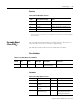
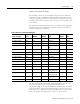
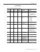
Table C.21 Analog Input Point Object Class Attributes
Attr ID
Access
Rule Name Data Type Description Semantics
3 Get Value REAL
4 Get Status BOOL Indicates if a fault or
alarm has occurred.
0 = Operating without alarms or
faults
1 = Alarm or fault condition
exists. The Value attribute may
not represent the actual field
value.
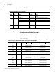
7 Get/Set Input Range USINT Valid range of the input
signal.
1 = 0 to 5 Volts
2 = 0 to 10 Volts
3 = 4 to 20 mA
6 = -5 to 5 Volts
7 = 1 to 5 Volts
8 = 0 to 20 mA
131 = 0 to 1 Volts
8 Get Value Data Type USINT Determines the data type
of the Value.
1 = REAL
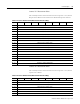
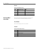
101 Get/Set Low
Engineering
REAL Low scaling value The measurement value
(measurement units) that
corresponds to either the low
Input Range (signal units) or
the sensor underrange fault.
103 Get/Set High
Engineering
REAL High scaling value The measurement value
(measurement units) that
corresponds to either the high
Input Range (signal units) or
the sensor overrange fault.
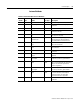
116 Get/Set Digital Filter UINT Controls the time
constant of the digital
filter.
Milliseconds
143 Get/Set Sensor Tag STRING2 A descriptive name for the
sensor or channel.
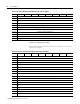
147 Get/Set Data Units ENGUNIT The data units of Value,
Low Engineering, and
High Engineering.
150 Get/Set Rate Value REAL The rate of change of the
analog input value.
Data Units per minute
151 Get/Set Rate Filter REAL Controls the time
constant of the rate filter.
Seconds