
Owner manual

Publication GMSI10-UM006C-EN-P - August 2010
20 Installing the XM-360 Process Module
Connecting the Power Supply
Power supplied to the module must be nominally 24 Vdc (±10%) and must be
a Class 2 rated circuit.
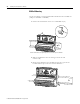
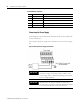
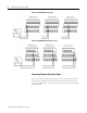
Wire the DC-input power supply to the terminal base unit as shown in Figure
2.8.
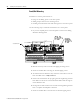
Figure 2.8 DC Input Power Supply Connections
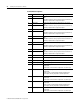
47 DNet V (+) DeviceNet bus power input, positive side (red wire)
48 DNet V (-) DeviceNet bus power input, negative side (black wire)
49 4-20mA 4 (-) 4-20mA output 4, negative side
50 4-20mA 5 (-) 4-20mA output 5, negative side
51 4-20mA 6 (-) 4-20mA output 6, negative side
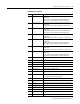
Terminal Block Assignments
No. Name Description
-
24V dc
Power
Supply
+
-
IMPORTANT
A Class 2 circuit can be provided by use of an NEC Class 2
rated power supply, or by using a SELV or PELV rated
power supply with a 5 Amp current limiting fuse installed
before the XM module(s).
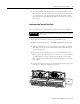
IMPORTANT
24Vdc needs to be wired to terminal 37 (+24 V In) to
provide power to the device and other XM modules linked
to the wired terminal base via the side connector.