
Owner manual

Publication GMSI10-UM006C-EN-P - August 2010
Installing the XM-360 Process Module 19
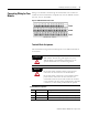
24 Vin (-) / Iin Sense 3 Voltage Input 3, negative side when channel configured as a
voltage input
Current sensing 3 terminal when channel configured as a
current input, must be jumpered to channel Input RTN
25 Vin (+) / Input In 4 Voltage Input 4, positive side when channel configured as a
voltage input
Current Input 4 when channel configured as a current input
26 Vin (-) / Iin Sense 4 Voltage Input 4, negative side when channel configured as a
voltage input
Current sensing 4 terminal when channel configured as a
current input, must be jumpered to channel Input RTN
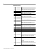
27 Vin (+) / Input In 5 Voltage Input 5, positive side when channel configured as a
voltage input
Current Input 5 when channel configured as a current input
28 Vin (-) / Iin Sense 5 Voltage Input 5, negative side when channel configured as a
voltage input
Current sensing 5 terminal when channel configured as a
current input, must be jumpered to channel Input RTN
29 Vin (+) / Input In 6 Voltage Input 6, positive side when channel configured as a
voltage input
Current Input 6 when channel configured as a current input
30 Vin (-) / Iin Sense 6 Voltage Input 6, negative side when channel configured as a
voltage input
Current sensing 6 terminal when channel configured as a
current input, must be jumpered to channel Input RTN
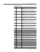
31 4-20mA 4 (+) 4-20mA output 4, positive side
32 4-20mA 5 (+) 4-20mA output 5, positive side
33 4-20mA 6 (+) 4-20mA output 6, positive side
34 4-20mA 1 (-) 4-20mA output 1, negative side
35 4-20mA 2 (-) 4-20mA output 2, negative side
36 4-20mA 3 (-) 4-20mA output 3, negative side
37 +24V In Connection to primary external +24V power supply, positive
side
38 24V Common Connection to external +24V power supply, negative side
(internally DC-coupled to circuit ground)
39 Reserved
40 Common Internally DC-coupled to circuit ground
41 Chassis Connection to DIN rail ground spring or panel mounting hole
42 Chassis Connection to DIN rail ground spring or panel mounting hole
43 Chassis Connection to DIN rail ground spring or panel mounting hole
44 CAN_High DeviceNet bus connection, high differential (white wire)
45 CAN_Low DeviceNet bus connection, low differential (blue wire)
46 CAN Shield DeviceNet bus connection to chassis ground (bare wire)
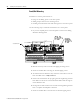
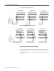
Terminal Block Assignments
No. Name Description