XM-360 Process Module User Guide Firmware Revision 5 1440-TPR06-00RE
Important User Information Solid state equipment has operational characteristics differing from those of electromechanical equipment. Safety Guidelines for the Application, Installation and Maintenance of Solid State Controls (publication SGI-1.1 available from your local Rockwell Automation sales office or online at http://literature.rockwellautomation.com) describes some important differences between solid state equipment and hardwired electromechanical devices.
Safety Approvals The following information applies when operating this equipment in hazardous locations. Informations sur l’utilisation de cet équipement en environnements dangereux. Products marked "CL I, DIV 2, GP A, B, C, D" are suitable for use in Class I Division 2 Groups A, B, C, D, Hazardous Locations and nonhazardous locations only. Each product is supplied with markings on the rating nameplate indicating the hazardous location temperature code.
Table of Contents Chapter 1 Introduction Introducing the XM-360 Process Module . . . . . . . . . . . . . . . . . . . . . . . 1 XM-360 Module Components. . . . . . . . . . . . . . . . . . . . . . . . . . . . . . . . . 2 Using this Manual. . . . . . . . . . . . . . . . . . . . . . . . . . . . . . . . . . . . . . . . . . . 2 Organization. . . . . . . . . . . . . . . . . . . . . . . . . . . . . . . . . . . . . . . . . . . . 3 Document Conventions . . . . . . . . . . . . . . . . . . . . . . . . . . . . . . . .
Table of Contents vi Appendix A Specifications . . . . . . . . . . . . . . . . . . . . . . . . . . . . . . . . . . . . . . . . . . . . . . . . . . . . . . . . . 61 Appendix B DeviceNet Information Electronic Data Sheets. . . . . . . . . . . . . . . . . . . . . . . . . . . . . . . . . . . . . . 67 Changing Operation Modes. . . . . . . . . . . . . . . . . . . . . . . . . . . . . . . . . . 67 Transition to Program Mode. . . . . . . . . . . . . . . . . . . . . . . . . . . . . . 68 Transition to Run Mode .
Table of Contents vii Parameter Object (Class ID 0FH). . . . . . . . . . . . . . . . . . . . . . . . . . . . . 92 Class Attributes . . . . . . . . . . . . . . . . . . . . . . . . . . . . . . . . . . . . . . . . 92 Instances. . . . . . . . . . . . . . . . . . . . . . . . . . . . . . . . . . . . . . . . . . . . . . 93 Instance Attributes. . . . . . . . . . . . . . . . . . . . . . . . . . . . . . . . . . . . . . 95 Services . . . . . . . . . . . . . . . . . . . . . . . . . . . . . . . . . . . . . . . . . . .
Table of Contents viii Publication GMSI10-UM006C-EN-P - August 2010
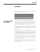
Chapter 1 Introduction This chapter provides an overview of the XM-360 Process module. It also discusses the components of the modules. For information about Introducing the XM-360 Process Module See page Introducing the XM-360 Process Module 1 XM-360 Module Components 2 Using this Manual 2 The XM-360 Process module is an intelligent 6-channel general-purpose process monitor.
2 Introduction The XM-360 consists of a terminal base unit and an instrument module. The XM-360 Process Module and the XM-944 Temperature Terminal Base are shown below. XM-360 Module Components Figure 1.1 XM-360 Module Components PROCESS XM-944 Temperature Module Terminal Base Unit Cat. No. 1440-TB-E 1440-TPR06-00RE XM-360 Process Module Cat. No.
Introduction 3 Organization To help you navigate through this manual, it is organized in chapters based on these tasks and topics. Chapter 1 “Introduction” contains an overview of this manual and the XM-360 module. Chapter 2 “Installing the XM-360 Process Module” describes how to install, wire, and use the XM-360 module. Chapter 3 “Configuration Parameters” provides a complete listing and description of the XM-360 parameters.
4 Introduction Publication GMSI10-UM006C-EN-P - August 2010
Chapter 2 Installing the XM-360 Process Module This chapter discusses how to install and wire the XM-360 Process module. It also describes the module indicators and the basic operations of the module.
6 Installing the XM-360 Process Module XM Installation Requirements This section describes wire, power and grounding requirements and instructions for an XM system. Wiring Requirements Use solid or stranded wire. All wiring should meet the following specifications: • 14 to 22 AWG copper conductors without pretreatment; 8 AWG required for grounding the DIN rail for electromagnetic interference (emi) purposes • Recommended strip length 8 millimeters (0.
Installing the XM-360 Process Module 7 Figure 2.
8 Installing the XM-360 Process Module IMPORTANT See Application Technique "XM Power Supply Solutions", publication ICM-AP005A-EN-E, for guidance in architecting power supplies for XM systems. Grounding Requirements Use these grounding requirements to ensure safe electrical operating circumstances, and to help avoid potential emi and ground noise that can cause unfavorable operating conditions for your XM system. Din Rail Grounding The XM modules make a chassis ground connection through the DIN rail.
Installing the XM-360 Process Module 9 Figure 2.
10 Installing the XM-360 Process Module Figure 2.3 DIN Rail Grounding Block Panel/Wall Mount Grounding The XM modules can also be mounted to a conductive mounting plate that is grounded. See Figure 2.5. Use the grounding screw hole provided on the terminal base to connect the mounting plate the Chassis terminals. Figure 2.
Installing the XM-360 Process Module 11 Figure 2.5 Panel/Wall Mount Grounding 1 Power Supply 1 Power Supply 1 Use 14 AWG wire.
12 Installing the XM-360 Process Module 24V Common Grounding 24 V power to the XM modules must be grounded. When two or more power supplies power the XM system, ground the 24 V Commons at a single point, such as the ground bus bar. IMPORTANT IMPORTANT If it is not possible or practical to ground the -24Vdc supply, then it is possible for the system to be installed and operate ungrounded.
Installing the XM-360 Process Module ATTENTION 13 Use of a separate DeviceNet power supply is not permitted. See Application Technique "XM Power Supply Solutions", publication ICM-AP005A-EN-E, for guidance in using XM with other DeviceNet products. For more information on the DeviceNet installation, refer to the ODVA Planning and Installation Manual - DeviceNet Cable System, which is available on the ODVA web site (http://www.odva.org).
14 Installing the XM-360 Process Module DIN Rail Mounting Use the steps below to mount the XM-944 terminal base unit on a DIN rail (A-B pt no. 199-DR1 or 199-DR4). 1. Position the terminal base on the 35 x 7.5mm DIN rail (A). Position terminal base at a slight angle and hook over the top of the DIN rail. 2. Slide the terminal base unit over leaving room for the side connector (B). 3.
Installing the XM-360 Process Module 15 4. Press down on the terminal base unit to lock the terminal base on the DIN rail. If the terminal base does not lock into place, use a screwdriver or similar device to open the locking tab, press down on the terminal base until flush with the DIN rail and release the locking tab to lock the base in place. Interconnecting Terminal Base Units Follow the steps below to install another terminal base unit on the DIN rail.
16 Installing the XM-360 Process Module Panel/Wall Mounting Installation on a wall or panel consists of: • laying out the drilling points on the wall or panel • drilling the pilot holes for the mounting screws • installing the terminal base units and securing them to the wall or panel Use the following steps to install the terminal base on a wall or panel. 1. Lay out the required points on the wall/panel as shown in the drilling dimension drawing below. Side Connector 2.
Installing the XM-360 Process Module 17 Wiring to the module is made through the terminal base unit on which the module mounts. The XM-360 is compatible only with the XM-944 terminal base unit, Cat. No. 1440-TB-E. Connecting Wiring for Your Module Figure 2.7 XM-944 Terminal Base Unit XM-944, Cat. No. 1440-TB-E Terminal Block Assignments The terminal block assignments and descriptions for the XM-360 module are shown below.
18 Installing the XM-360 Process Module Terminal Block Assignments Publication GMSI10-UM006C-EN-P - August 2010 No.
Installing the XM-360 Process Module 19 Terminal Block Assignments No.
20 Installing the XM-360 Process Module Terminal Block Assignments No. Name Description 47 DNet V (+) DeviceNet bus power input, positive side (red wire) 48 DNet V (-) DeviceNet bus power input, negative side (black wire) 49 4-20mA 4 (-) 4-20mA output 4, negative side 50 4-20mA 5 (-) 4-20mA output 5, negative side 51 4-20mA 6 (-) 4-20mA output 6, negative side Connecting the Power Supply Power supplied to the module must be nominally 24 Vdc (±10%) and must be a Class 2 rated circuit.
Installing the XM-360 Process Module ATTENTION 21 The power connections are different for different XM modules. Refer to the installation instructions for your specific XM module for complete wiring information. Connecting the 4-20mA Outputs The module includes six 4-20mA output channels into a maximum load of 600 ohms each. The 4-20mA outputs are arranged into two isolated banks of three outputs each.
22 Installing the XM-360 Process Module Figure 2.9 4-20mA Output Connections Figure 2.10 4-20mA Output Connections cont. Connecting a Remote Relay Reset Signal If you set the relay to latching and the relay activates, the relay stays activated even when the condition that caused the alarm has ended. The remote relay reset signal enables you to reset the relay remotely after you have corrected the alarm condition.
Installing the XM-360 Process Module 23 The XM-360 does not have an on-board relay. The relays are added when an Expansion Relay (XM-441) module is connected to the XM-360. The XM-360 supports two Expansion Relay modules for a total of eight relays.. IMPORTANT You must enable the Enable Relay Reset Switch Terminals parameter to make the Channel 6 input terminals available to wire the external relay reset switch. Refer to General Parameters on page 44.
24 Installing the XM-360 Process Module A single switch contact can also be shared by multiple XM-360 modules wired in series as shown in Figure 2.12. When multiple modules are wired to a single switch, only one 4-20mA output channel is necessary to supply all the modules. ATTENTION IMPORTANT TIP The relay reset connections may be different for different XM modules. Figure 2.12 applies only to the XM-360 module. Refer to the installation instructions for the module for its terminal assignments.
Installing the XM-360 Process Module 25 Connecting the Inputs The XM-360 will accept signals from loop currents or voltage inputs. All six input channels are electrically isolated from each other and from circuit power and ground. The isolation provided is up to 250V. IMPORTANT With all the cable shields connected (six individual input cables and six output cables), there are not enough chassis terminals for each shield.
26 Installing the XM-360 Process Module Figure 2.14 0–5V Voltage Input to Channel 2 Wiring TYPICAL WIRING FOR VOLTAGE INPUT TO XM-360 PROCESS MODULE CHANNEL 2 Process RED Output V out Voltage Com BLK 21 22 RED BLK 41 SHIELD Figure 2.
Installing the XM-360 Process Module 27 Figure 2.16 0–5V Voltage Input to Channel 4 Wiring TYPICAL W IRING FOR VO LTAGE INPUT TO XM-36 0 PRO CESS MO DULE CHANNEL 4 Process RED Output V out Voltage Com BLK 42 RED BLK SHIELD 25 26 Figure 2.
28 Installing the XM-360 Process Module Figure 2.18 0–5V Voltage Input to Channel 6 Wiring TYPICAL WIRING FOR VOLTAGE INPUT TO XM-360 PROCESS MODUL E CHANNEL 6 43 Process Output V out RED Voltage Com BLK RED BLK SHIELD 29 30 Connecting a Loop-Powered 4-20mA Input Figures 2.19 to 2.24 show the wiring from a loop-powered 4-20mA input to the terminal base unit of the XM-360. ATTENTION TIP Publication GMSI10-UM006C-EN-P - August 2010 You may ground the cable shield at either end of the cable.
Installing the XM-360 Process Module 29 Figure 2.19 Loop-powered 4-20mA to Channel 1 Wiring TYPICAL WIRING FOR LOOP-POWERED 4-20mA TO XM-360 PROCESS MODULE CHANNEL 1 19 20 3 4 41 - BLK 4-20mA Transmitter + RED BLK RED SHIELD - Loop Power Supply 24V + Figure 2.
30 Installing the XM-360 Process Module Figure 2.21 Loop-powered 4-20mA to Channel 3 Wiring TYPICAL WIRING FOR LOOP-POWERED 4-20mA TO XM-360 PROCESS MODULE CHANNEL 3 - BLK 4-20mA Transmitter + RED 42 BLK RED 23 24 7 8 SHIELD - Loop Power Supply 24V + Figure 2.
Installing the XM-360 Process Module 31 Figure 2.23 Loop-powered 4-20mA to Channel 5 Wiring TYPICAL WIRING FOR LOOP-POWERED 4-20mA TO XM-360 PROCESS MODULE CHANNEL 5 - BLK 4-20mA Transmitter + RED BLK RED 43 27 28 SHIELD + 11 12 Loop Power Supply 24V Figure 2.
32 Installing the XM-360 Process Module Connecting a 4-20mA / 0-20mA Input Figures 2.25 to 2.30 show the wiring from a non-loop powered 4-20mA input to the terminal base unit of the XM-360. ATTENTION TIP You may ground the cable shield at either end of the cable. Do not ground the shield at both ends. Recommended practice is to ground the cable shield at the XM-360 terminal base and not at the field device. Any convenient Chassis terminal may be used (see Terminal Block Assignments on page 17).
Installing the XM-360 Process Module 33 Figure 2.26 Non-loop Powered 4-20mA Input to Channel 2 Wiring TYPICAL WIRING FOR NON-LOOP POWERED 4-20mA INPUT TO XM-360 PROCESS MODULE CHANNEL 2 + RED 4-20mA Transmitter - BLK RED BLK SHIELD 21 22 41 5 6 Figure 2.
34 Installing the XM-360 Process Module Figure 2.28 Non-loop Powered 4-20mA Input to Channel 4 Wiring TYPICAL WIRING FOR NON-LOOP POWERED 4-20mA INPUT TO XM-360 PROCESS MODULE CHANNEL 4 + RED 4-20mA Transmitter - BLK RED BLK 42 SHIELD 25 26 9 10 Figure 2.
Installing the XM-360 Process Module 35 Figure 2.30 Non-loop Powered 4-20mA Input to Channel 6 Wiring TYPICAL WIRING FOR NON-LOOP POWERED 4-20mA INPUT TO XM-360 PROCESS MODULE CHANNEL 6 43 RED + 4-20mA Transmitter BLK RED BLK 29 30 SHIELD 13 14 PC Serial Port Connection The XM-360 includes a serial connection that allows you to connect a PC to it and configure the module’s parameters. The connection is through a mini-connector that is located on top of the XM-360, as shown below. Figure 2.
36 Installing the XM-360 Process Module connector, and the connector that inserts into the module is a USB Mini-B male connector. WARNING IMPORTANT If you connect or disconnect the serial cable with power applied to the module or the serial device on the other end of the cable, an electrical arc can occur. This could cause an explosion in hazardous location installations. Be sure that power is removed or the area is nonhazardous before proceeding.
Installing the XM-360 Process Module ATTENTION ATTENTION ATTENTION IMPORTANT 37 You must ground the DeviceNet shield at only one location. Connecting the DeviceNet shield to terminal 46 will ground the DeviceNet shield at the XM-360 module. If you intend to terminate the shield elsewhere, do not connect the shield to terminal 46. The DeviceNet network must also be referenced to earth at only one location. Connect DNet V- to earth or chassis at one of the XM modules.
38 Installing the XM-360 Process Module Mounting the Module The XM-360 mounts on the XM-944 terminal base unit, Cat. No. 1440-TB-E. You should mount the module after you have connected the wiring on the terminal base unit. ATTENTION The XM-360 is compatible only with the XM-944 terminal base unit. The keyswitch on the terminal base unit should be at position 5 for the XM-360. Do not attempt to install XM-360 modules on other terminal base units.
Installing the XM-360 Process Module 39 2. Make certain the side connector (B) is pushed all the way to the left. You cannot install the module unless the connector is fully extended. 3. Make sure that the pins on the bottom of the module are straight so they will align properly with the connector in the terminal base unit. 4. Position the module (D) with its alignment bar (E) aligned with the groove (F) on the terminal base. 5. Press firmly and evenly to seat the module in the terminal base unit.
40 Installing the XM-360 Process Module Module Status (MS) Indicator Color State Description No color Off No power applied to the module. Green Flashing Red Module performing power-up self test. Flashing Module operating in Program Mode1. Solid Module operating in Run Mode2. Flashing • Application firmware is invalid or not loaded. Download firmware to the module. Red • Firmware download is currently in progress. • The module power voltage is incorrect.
Installing the XM-360 Process Module 41 Channel Status Indicator (6 in all) Color State Description No Color Off • Normal operation within alarm limits on the channel. • No power applied to the module, look at Module Status LED. Basic Operations Yellow Solid An alert level alarm condition exists on the channel (and no sensor-out-of-range or danger level alarm condition exists). Red Solid A danger level alarm condition exists on the channel (and no sensor-out-of-range condition exists).
42 Installing the XM-360 Process Module Manually Resetting Relays The XM-360 has an external reset switch located on top of the module, as shown in Figure 2.33. Figure 2.33 Reset Switch 1440-TUN06-00RE PROCESS Press the Reset Switch to reset the relays The switch can be used to reset all latched relays in the Expansion Relay module when it is connected to the XM-360.
Chapter 3 Configuration Parameters This chapter provides a complete listing and description of the XM-360 parameters. The parameters can be viewed and edited using the XM Serial Configuration Utility software and a personal computer. If the module is installed on a DeviceNet network, configuring can also be performed using a network configuration tool such as RSNetWorx (Version 3.0 or later). Refer to your configuration tool documentation for instructions on configuring a device.
44 Configuration Parameters General Parameters Use the general parameters to configure the sensor out-of-range allowance and to enable the relay reset switch terminals on the XM-360 module. General Parameters Parameter Name Description Values/Comments Sensor OOR Allowance 0 to 5% The margin beyond the Input Range (as a percentage of full scale) that will be considered valid and will not cause a sensor out-of-range fault.
Configuration Parameters 45 Channel Parameters Parameter Name Description Values/Comments Sensor Input Range Defines the valid range of the input signal. Options: 0 to 5 Volts 0 to 10 Volts 4 to 20 mA -5 to 5 Volts 1 to 5 Volts 0 to 20 mA 0 to 1 Volt Data Units Defines the data units of the measured value.
46 Configuration Parameters Channel Parameters Parameter Name Description Measurement Time Constant The time constant used for smoothing (low-pass filtering) of the measurement value. Values/Comments XM Configuration Utility EDS File Seconds Milliseconds Note: The greater the measurement time constant, the slower the response of the measured value to change in the input signal (less sensitive to noise in the signal).
Configuration Parameters 47 Alarm Parameters Parameter Name Description Values/Comments Number (XM Serial Configuration Utility only) Sets the type of measurement and channel that is associated with the alarm. There are 12 alarms in the XM-360. Each alarm is associated with a measurement.
48 Configuration Parameters Alarm Parameters Parameter Name Description Values/Comments Condition Controls when the alarm should trigger. Options: Greater Than Less Than Inside Range Outside Range • Greater than - Triggers the alarm when the measurement value is greater than or equal to the Alert and Danger Threshold values. The Danger Threshold value must be greater than or equal to the Alert Threshold value for the trigger to occur.
Configuration Parameters 49 Alarm Parameters Parameter Name Description Values/Comments Hysteresis The amount that the measured value must fall (below the threshold) before the alarm condition is cleared. For example, Alert Threshold = 120 and Hysteresis = 2. The alarm (alert) activates when the measured value is 120 and will not clear until the measured value is 118. Same measurement unit as Data Units selection for the specified channel. Note that for rate alarms, it is unit per minute.
50 Configuration Parameters Relay Parameters Parameter Name Description Options/Comments Name (XM Serial Configuration Utility only) A descriptive name to help identify the relay in the XM Serial Configuration Utility. Maximum 18 characters Enable Enable/disable the selected relay. Note: The Relay Current Status is set to "Not Activated" when the relay is disabled. See page 58.
Configuration Parameters 51 Relay Parameters Parameter Name XM Configuration EDS File Utility Alarm A/B Alarm Identifier A/B Description Options/Comments Sets the alarm(s) that the relay will monitor. The alarm must be from the same device as the relay. When the Activation Logic is set to "A and B" or "A or B," you can select an alarm in both Alarm A and Alarm B. The system monitors both alarms. When the Activation Logic is set to "A Only," you can select an alarm only in Alarm A.
52 Configuration Parameters Relay Parameters Parameter Name Description XM Configuration EDS File Utility Failsafe Relay Failsafe Option Determines whether the relay is failsafe or nonfail-safe. Failsafe operation means that when in alarm, the relay contacts are in their "normal," de-energized, or "shelf-state" positions. In other words, normally closed relays are closed in alarm, and normally open relays are open in alarm. With failsafe operation, a power failure equals an alarm.
Configuration Parameters 4-20mA Output Parameters 53 The 4-20mA output parameters define the characteristics of the 4-20mA output signals. The XM-360 supports a total of six 4-20mA outputs. Each output is permanently associated with a corresponding channel. The parameters are the same for each output. IMPORTANT If the Enable Relay Reset Switch Terminals parameter is enabled, Channel 6 is not available for configuration, and the Channel 6 4-20mA output is set to a fixed (12mA) level.
54 Configuration Parameters IMPORTANT The 4-20mA outputs are either on or off. When they are on, the 4-20mA outputs overshoot the 4 and 20mA limits by 10% when the measurement exceeds the minimum and maximum range. This means the minimum current produced is 3.6mA and the maximum current produced is 22mA. When the 4-20mA outputs are off, they produce a current approximately 2.9mA. The 4-20mA outputs are off under the following conditions: • The 4-20mA outputs are set to "Disable" (see Enable above).
Configuration Parameters 55 trend records, the interval between trend records, and which relay triggers (activates) the collection of the trend data. IMPORTANT The Triggered Trend parameters are not included in the EDS file and cannot be edited using generic configuration tools such as RSNetWorx for DeviceNet. Triggered Trend Parameters Parameter Name Description Values/Comments Enable Triggered Trend Measurements Enables/disables the triggered trend measurements.
56 Configuration Parameters Triggered Trend Parameters Parameter Name Description Values/Comments Post Trigger The percentage of records to be collected once the trigger occurs. For example, if you set Post Trigger to 20%, then 80% of the records in the trend are before the trigger occurs, and 20% of the records in the trend are after the trigger occurs. 0 to 100 Percent This allows you to evaluate what happened after the trigger occurred. Status Shows the status of the trend data.
Configuration Parameters I/O Data Parameters 57 The I/O data parameters are used to configure the content and size of the DeviceNet I/O Poll response message. IMPORTANT The XM-360 must be free of Poll connections when configuring the Poll Output (Poll Response Assembly) and Poll Size. Any attempt to download the parameters while a master device has established the Poll connection with the XM-360 will result in an error.
58 Configuration Parameters The Data parameters are used to view the measured values of the input channels and the 4–20mA outputs, as well as to monitor the status of the channels, alarms, and relays. Data Parameters TIP To view all the data parameters in the XM Serial Configuration Utility, click the View Data tab. Channel Data Parameters Channel Data Parameters Parameter Name Description Values/Comments Channel Status States whether a fault exists on the associated channel.
Configuration Parameters 59 Alarm and Relay Status Parameters Alarm and Relay Status Parameters Parameter Name Description Values/Comments Alarm Status States the current status of the measurement value, rate of change and difference alarm. Possible status values: States the current status of the relay.
60 Configuration Parameters Device Mode Parameters The Device Mode parameters are used to control the functions and the behavior of the device. IMPORTANT The XM Serial Configuration Utility handles these parameters automatically and transparently to the user. Device Mode Parameters Parameter Name Description Values/Comments Device Mode Sets the current operation mode of the device. Refer to Changing Operation Modes on page 67 for more information.
Appendix A Specifications Appendix A lists the technical specifications for the XM-360 Process module. XM-360 Technical Specifications Product Feature Specification Communications DeviceNet Standard DeviceNet protocol for all functions NOTE: The XM-360 uses only the DeviceNet protocol, not power. Module power is provided independently.
62 Specifications XM-360 Technical Specifications Product Feature Specification Inputs 6 Channels 1 to 6 process DC voltage inputs or loop current inputs Isolation Up to 250 Volts of isolation for each input Sensitivity User configurable in software.
Specifications 63 XM-360 Technical Specifications Product Feature Specification Signal Conditioning Accuracy 1% of full scale max ±0.2% of full scale typical Low Pass Filter User configurable for the measurement value and rate of change value from each channel Resolution 0.
64 Specifications XM-360 Technical Specifications Product Feature Specification Relays Number Up to eight relays when interconnected to one or two XM-441 Expansion Relay modules, or Eight virtual relays whose status can be used by remote control systems Failsafe Normally energized (failsafe), or Normally de-energized (non-fail-safe) Latching Latching, or Non-latching Time Delay 0 to 25.
Specifications 65 XM-360 Technical Specifications Product Feature Specification Environmental Operating Temperature -20 to +65°C (-4 to +149°F) Storage Temperature -40 to +85°C (-40 to +185°F) Relative Humidity 95% non-condensing Conformal Coating All printed circuit boards are conformally coated in accordance with IPC-A-610C, Physical Dimensions Height: 3.8in (97mm) Width: 3.7in (94mm) Depth: 3.7in (94mm) Terminal Screw Torque 7 pound-inches (0.
66 Specifications Publication GMSI10-UM006C-EN-P - August 2010
Appendix B DeviceNet Information Electronic Data Sheets Electronic Data Sheet (EDS) files are simple text files used by network configuration tools such as RSNetWorx (Version 3.0 or later) to help you identify products and easily commission them on a network. The EDS files describe a product’s device type, product revision, and configurable parameters on a DeviceNet network. The EDS files for the XM modules are installed on your computer with the XM configuration software.
68 DeviceNet Information Transition to Program Mode Parameter values can only be downloaded to an XM module while the module is in Program mode. Any attempt to download a parameter value while the module is in Run mode will result in a Device State Conflict error. To transition an XM module from Run mode to Program mode on a DeviceNet network, set the Device Mode parameter to "Program mode" and click Apply.
DeviceNet Information 69 The table below defines the services supported by the XM modules. The table includes the service codes, classes, instances, and attributes by their appropriate hexidecimal codes. Use the Class Instance Editor in RSNetWorx to execute these services, as illustrated in the example below.
70 DeviceNet Information Example To save the configuration parameters to the non-volatile memory (EEPROM), fill in the Class Instance Editor as shown below. Clear Send the attribute ID and then enter the Class (320 hex) and Instance (1) Select the Save service code Click Execute to initiate the action Invalid Configuration Errors A Start or Save service request to an XM module may return an Invalid Device Configuration error when there is a conflict amongst the configuration settings.
DeviceNet Information 71 Additional Error Codes returned with the Invalid Device Configuration Error (0xD0) XM-360 I/O Message Formats Error Code (Hex) Description 0A Too many alarms associated with a single measurement. 0B Invalid node address in the alarm list. 0C Too many alarms in the alarm list. Or, no alarms in the alarm list. 0D Alarm levels cannot be zero for alarms that are enabled. 0E Too many slaves in the scanner’s input data table.
72 DeviceNet Information The Poll response data can also be requested explicitly through Assembly Object (Class ID 0x4), Instance 101 (0x65) – 103 (0x67), Data Attribute (3). The following tables show the static data format of Assembly instance 101– 103.
DeviceNet Information 73 XM-360 Assembly Instance 103 Data Format Byte Definition 0–3 Channel 1 measurement value 4–7 Channel 1 rate of change value 8-11 Channel 2 measurement value 12-15 Channel 2 rate of change value 16-19 Channel 3 measurement value 20-23 Channel 3 rate of change value 24-27 Channel 4 measurement value 28-31 Channel 4 rate of change value 32-35 Channel 5 measurement value 36-39 Channel 5 rate of change value 40-43 Channel 6 measurement value 44-47 Channel 6 rat
74 DeviceNet Information XM Status Values The following tables describe the XM Status values that are included in the COS messages.
DeviceNet Information 75 Figure B.1 Bit-Strobe Command The XM modules use the bit received in a Bit-Strobe connection as a trigger event. When the bit number corresponding to the XM module’s node address is set, the XM module will collect the triggered trend data. Note that the XM modules do not send data in the Bit-Strobe response. ADR for XM Modules Automatic Device Replacement (ADR) is a feature of an Allen-Bradley DeviceNet scanner.
76 DeviceNet Information • The ADR scanner can not download the configuration data to an XM module if the module has a saved configuration in its non-volatile memory. This happens because the saved configuration is restored and the module enters Run mode when the power is cycled. (Configuration parameters cannot be downloaded while an XM module is in Run mode.) XM modules must be in Program mode for the ADR configuration to be downloaded and this occurs only when there is no saved configuration.
DeviceNet Information 77 – All SU/CD Trend related parameters – Custom Assembly structure (see page 57) • The ADR and trigger group functions cannot be used together. A module can have only one primary master so a module cannot be both configured for ADR and included in a trigger group. The ADR scanner must be the primary master for the modules configured for ADR. The XM-440 Master Relay module must be the primary master for modules included in a trigger group.
78 DeviceNet Information Publication GMSI10-UM006C-EN-P - August 2010
Appendix C DeviceNet Objects Appendix C provides information on the DeviceNet objects supported by the XM-360 module.
80 DeviceNet Objects The Identity Object provides identification and general information about the device. Identity Object (Class ID 01H) Class Attributes The Identity Object provides no class attributes. Instance Attributes Table C.
DeviceNet Objects 81 Table C.2 Identity Object Status Bit Name Description 4 Boot Program Vendor-specific, indicates that the boot program is running. The Main Application must be corrupt or missing. 5-7 Vendor-specific, not implemented 8 Minor Recoverable Fault Set whenever there is a sensor out of range. Also set if the ambient temperature is measured to be outside of the module’s operating range.
82 DeviceNet Objects Class Attributes Table C.4 DeviceNet Object Class Attributes Attr ID Access Rule Name Data Type Default Value 1 Get Revision UINT 2 Instance Attributes Table C.
DeviceNet Objects 83 Services Table C.6 DeviceNet Object Services Service Code Class/Instance Usage Name 0Eh Class/Instance Get_Attribute_Single 10h Instance Set_Attribute_Single1 4Bh Instance Allocate_Master/Slave_Connetion_Set 4Ch Instance Release_Group_2_Identifier_Set 1 Attributes can only be set while the device is in Program Mode. See the description of the Device Mode Object for more information.
84 DeviceNet Objects Instance Attributes Table C.9 Assembly Object Instance Attributes Attr ID Access Rule Name Data Type Value 1 Get Number of Members in list UINT Only supported for Dynamic Assembly instance 2 Set Member List Array of STRUCT: Only supported for Dynamic Assembly instance Member Data Description 3 Get UINT Size of member data value in bits Member Path Size UINT Member Path Packed EPATH Data Defined in tables on the following pages.
DeviceNet Objects 85 Instance 101 - Measurement Values This assembly instance can be selected to be sent in response to an I/O Poll Request from a Master. This instance is the default Poll response selection. Table C.
86 DeviceNet Objects Table C.
DeviceNet Objects 87 Instance 199 - Dynamic Assembly This Assembly instance can be created and configured with the XM Serial Configuration Utility or RSMACC Enterprise Online Configuration Utility. Using the configuration software, you determine the format of the data. This assembly instance can be selected to be sent in response to an I/O Poll request from a Master. The dynamic Assembly can include all of the measurement values included in Assembly instance 101.
88 DeviceNet Objects Services Table C.15 Assembly Object Services Connection Object (Class ID 05H) Service Code Class/Instance Usage Name 0Eh Class/Instance Get_Attribute_Single 10h Instance Set_Attribute_Single 08h Class Create 09h Instance Delete The Connection Object allocates and manages the internal resources associated with both I/O and Explicit Messaging Connections. Class Attributes The Connection Object provides no class attributes. Instances Table C.
DeviceNet Objects 89 Instance Attributes Table C.17 Connection Object Instance Attributes Attr ID Access Rule Name Data Type Description 1 Get State USINT State of the object. 2 Get Instance Type USINT Indicates either I/O or Messaging Connection. 3 Get Transport Class Trigger BYTE Defines behavior of the Connection. 4 Get Produced Connection ID UINT Placed in CAN Identifier Field when the Connection transmits.
90 DeviceNet Objects Services Table C.18 Connection Object Services Service Code Class/Instance Usage Name 05h Instance Reset 0Eh Instance Get_Attribute_Single 10h Instance Set_Attribute_Single The Analog Input Point Object models simple analog measurements performed by the XM-360 module. There are six instances of the Analog Input Point object, one for each input channel. Analog Input Point Object (Class ID 0AH) Class Attributes Table C.
DeviceNet Objects 91 Instance Attributes Table C.21 Analog Input Point Object Class Attributes Attr ID Access Rule Name Data Type 3 Get Value REAL 4 Get Status 7 Get/Set Input Range 8 Get 101 Description Semantics BOOL Indicates if a fault or alarm has occurred. 0 = Operating without alarms or faults 1 = Alarm or fault condition exists. The Value attribute may not represent the actual field value. USINT Valid range of the input signal.
92 DeviceNet Objects Services Table C.22 Analog Input Point Object Services Service Code Class/Instance Usage Name Description 0Eh Class/Instance Get_Attribute_Single Returns the contents of the specified attribute. 10h Instance Set_Attribute_Single Sets the contents of the specified attribute.1 1 Attributes can only be set while the device is in Program Mode. See the description of the Device Mode Object for more information.
DeviceNet Objects 93 Instances There are 38 instances of this object. Table C.
94 DeviceNet Objects Table C.
DeviceNet Objects 95 Table C.
96 DeviceNet Objects Table C.25 Parameter Object Instance Attributes Attr ID Access Rule Name Data Type Description 3 Get Link Path ARRAY of DeviceNet path DeviceNet path to the object for the Parameter value. Segment Type/Port BYTE See DeviceNet Specification Volume 1 Appendix I for format. Segment Address Semantics See DeviceNet Specification Volume 1 Appendix I for format.
DeviceNet Objects 97 Class Attributes The Acknowledge Handler Object provides no class attributes. Instances A module provides only a single instance (instance 1) of the Acknowledge Handler Object. This instance is associated with instance 4 of the Connection Object, the slave COS connection to a higher level master. Instance Attributes Table C.
98 DeviceNet Objects Instances There are 18 instances of this object. Instances 1-6 are associated with the 6 AIP Object measurement values. Instances 7-12 are associated with the 6 AIP Object rate values. And instances 13-18 are associated with the 6 Parameter Object difference calculations. Instance Attributes Table C.29 Alarm Object Instance Attributes Attr ID Access Rule Name Data Type Description Semantics 3 Get Alarm Status 3 BITS The current status of the alarm.
DeviceNet Objects 99 Table C.29 Alarm Object Instance Attributes Attr ID Access Rule 11 Name Data Type Description Semantics Get/Set Danger Threshold Low REAL The lesser threshold value for the danger (shutdown) condition for the range condition types. 12 Get/Set Hysteresis REAL The amount on the safe side of a threshold by which the value must recover to clear the alarm. 18 Get/Set Name STRING2 A name to help identify this alarm. Services Table C.
100 DeviceNet Objects Instance Attributes Table C.31 Device Mode Object Instance Attributes Attr ID Access Rule Name Data Type Description 3 Get/Set Device Mode UINT The operating mode of the 0 = Power Up module. 1 = RUN 2 = PROGRAM 199 Set Backdoor Service USINT Setting this attribute is equivalent to requesting the specified service.
DeviceNet Objects 101 Table C.32 Device Mode Object Services Service Code Class/Instance Usage Name Description 16h Instance Save Validate the device configuration settings if necessary and save them to non-volatile memory. 09h Instance Delete Delete the saved configuration from non-volatile memory. 15h Instance Restore Load the saved configuration or the factory default configuration from non-volatile memory. The Relay Object models a relay (actual or virtual).
102 DeviceNet Objects Instance Attributes Table C.34 Relay Object Instance Attributes Attr ID Access Rule Name Data Type Description Semantics 3 Get Relay Status BOOL The current status of the relay. 0 = Off 1 = On 4 Get/Set Relay Enable BOOL Indicates whether this relay object is enabled. 0 = Disabled 1 = Enabled 5 Get/Set Latch Enable BOOL Indicates whether this relay latches (requires a reset command to deactivate).
DeviceNet Objects 103 Table C.34 Relay Object Instance Attributes Attr ID Access Rule Name Data Type Description Semantics 14 Get Relay Installed BOOL Indicates whether an actual relay is associated with this instance. 0 = Not installed 1 = Installed Services Table C.35 Relay Object Services Service Code Class/Instance Usage Name Description 05h Class/Instance Reset Resets latched relay. 0Eh Class/Instance Get_Attribute_Single Returns a single attribute.
104 DeviceNet Objects Instance Attributes Table C.36 4-20mA Output Object Instance Attributes Attr ID Access Rule Name Data Type Description Semantics 3 Get/Set Value REAL The current output value. mA 4 Get/Set Enable BOOL Indicates whether this 4-20mA output is enabled. 0 = Disabled 1 = Enabled 5 Get/Set Max Range REAL The measured value associated with 20mA. 6 Get/Set Min Range REAL The measured value associated with 4mA.
Glossary alarm An alarm alerts you to a change in a measurement. For example, an alarm can notify you when the measured vibration level for a machine exceeds a pre-defined value. Automatic Device Replacement (ADR) A means for replacing a malfunctioning device with a new unit, and having the device configuration data set automatically. The ADR scanner uploads and stores a device’s configuration.
Glossary 106 Change of State (COS) DeviceNet communications method in which the XM module sends data based on detection of any changed value within the input data (alarm or relay status). current configuration The current configuration is the most recently loaded set of configuration parameters in the XM module’s memory. When power is cycled, the current configuration is loaded with either the saved configuration (in EEPROM) or the factory defaults (if there is no saved configuration).
Glossary 107 • Instructions for a task. • Definition of a term. MAC ID See node address. master device A device which controls one or more slave devices. The XM-440 Master Relay module is a master device. Node Address A DeviceNet network can have as many as 64 devices connected to it. Each device on the network must have a unique node address between 0 and 63. Node address 63 is the default used by uncommissioned devices. Node address is sometimes called “MAC ID.
Glossary 108 slave device A device that receives and responds to messages from a Master device but does not initiate communication. Slave devices include the XM measurement modules, such as the XM-120 Dynamic Measurement module and the XM-320 Position module. Strobe See Bit-Strobe. trend A set of records of one or more measurement parameter(s) collected at regular intervals of a base parameter such as time. trigger An event that prompts the collection of trend data.
Index Numerics 24V common grounding requirements 12 4-20mA Output Object 103 4-20mA output parameters 53 4-20mA Output 53 Enable 53 Max Range 53 Measurement 53 Min Range 53 4-20mA outputs, wiring 21 A Acknowledge Handler Object 96 Alarm 59 Alarm Object 97 alarm parameters 46 Alert Threshold (High) 48 Alert Threshold (Low) 48 Condition 48 Danger Threshold (High) 48 Danger Threshold (Low) 48 Enable 47 Hysteresis 49 Name 47 Number 47 Analog Input Point Object 90 Assembly Object 83 Automatic Device Replacemen
110 Index DeviceNet information automatic device replacement (ADR) 75 EDS files 67 I/O message formats 71 invalid device configuration errors 70 setting the Device Mode parameter 67 XM services 69 DeviceNet Object 81 DeviceNet objects 4-20mA Output 103 Acknowledge Handler 96 Alarm 97 Analog Input Point 90 Assembly 83 Connection 88 Device Mode 99 DeviceNet 81 Identity 80 Parameter 92 Relay 101 DIN Rail Grounding Block 9 DIN rail grounding requirements 8 document conventions 3 E Electronic Data Sheet (EDS)
Index poll message format 71 Assembly instance 101 72 Assembly instance 102 72 Assembly instance 103 73 power requirements 6 power supply, wiring 20 program mode 40, 67 R Relay Object 101 relay parameters 49 Activation Delay 50 Activation Logic 50 Alarm A 51 Alarm B 51 Alarm Identifier A 51 Alarm Identifier B 51 Alarm Levels 51 Alarm Status to Activate On (Alarm Levels) 51 Enable 50 Failsafe 52 Latching 50 Name 50 Number 49 Relay Installed 51 relays resetting 22, 42 remote relay reset signal, wiring 22 re
112 Index XM-944 terminal base description 2 mounting 13 wiring 17 Publication GMSI10-UM006C-EN-P - August 2010
Rockwell Automation Support Rockwell Automation provides technical information on the Web to assist you in using its products. At http://support.rockwellautomation.com, you can find technical manuals, a knowledge base of FAQs, technical and application notes, sample code and links to software service packs, and a MySupport feature that you can customize to make the best use of these tools.