Installation Instructions XM Dynamic Measurement Module Terminal Base Catalog Number 1440-TBS-J Topic Page Important User Information 2 Environment and Enclosure 3 North American Hazardous Location Approval 4 European Hazardous Location Approval 5 Prevent Electrostatic Discharge 6 About the Terminal Base 6 Before You Begin 8 Power Requirements 8 Wiring Requirements 9 Grounding Requirements 9 Terminating Resistors 11 Install the Terminal Base 12 Mount on a DIN Rail 12 Interconnec
XM Dynamic Measurement Module Terminal Base Important User Information Solid state equipment has operational characteristics differing from those of electromechanical equipment. Safety Guidelines for the Application, Installation and Maintenance of Solid State Controls (Publication SGI-1.1 available from your local Rockwell Automation sales office or online at http://www.rockwellautomation.
XM Dynamic Measurement Module Terminal Base 3 Environment and Enclosure ATTENTION This equipment is intended for use in a Pollution Degree 2 industrial environment, in overvoltage Category II applications (as defined in IEC 60664-1), at altitudes up to 2000 m (6562 ft) without derating. This equipment is not intended for use in residential environments and may not provide adequate protection to radio communication services in such environments. This equipment is supplied as open-type equipment.
XM Dynamic Measurement Module Terminal Base North American Hazardous Location Approval The following information applies when operating this equipment in hazardous locations. Informations sur l’utilisation de cet équipement en environnements dangereux. Products marked "CL I, DIV 2, GP A, B, C, D" are suitable for use in Class I Division 2 Groups A, B, C, D, Hazardous Locations and nonhazardous locations only.
XM Dynamic Measurement Module Terminal Base 5 European Hazardous Location Approval The following applies when the product bears the Ex Marking. This equipment is intended for use in potentially explosive atmospheres as defined by European Union Directive 94/9/EC and has been found to comply with the Essential Health and Safety Requirements relating to the design and construction of Category 3 equipment intended for use in Zone 2 potentially explosive atmospheres, given in Annex II to this Directive.
XM Dynamic Measurement Module Terminal Base WARNING WARNING WARNING This equipment must be used only with ATEX-certified Allen-Bradley backplanes. Secure any external connections that mate to this equipment by using screws, sliding latches, threaded connectors, or other means provided with this product. Do not disconnect equipment unless power has been removed or the area is known to be nonhazardous.
XM Dynamic Measurement Module Terminal Base 7 The 1440-TBS-J uses spring-clamp termination.
XM Dynamic Measurement Module Terminal Base Before You Begin To effectively use the terminal base, note the following considerations. Power Requirements Use a single Class 2 power supply to power the XM modules. Total current draw through the side connector cannot exceed 3 A. Refer to the specification for the specific modules for power requirements.
XM Dynamic Measurement Module Terminal Base 9 Wiring Requirements Use solid or stranded wire. All XM wiring must meet the following specifications: • 2.1…0.34 mm² (22…14 AWG) copper conductors without pretreatment; 8.4 mm² (8 AWG) or 1 in. copper required for grounding the DIN rail for electromagnetic interference (EMI) purposes • Recommended strip length 8 mm (0.31 in.
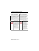
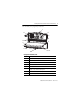
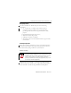
XM Dynamic Measurement Module Terminal Base DIN Rail Grounding Block To Earth Ground 8.4 mm² (AWG 8) Wire Din Rail Grounding Block Cat. No. 1492-WG10 24V Common Grounding The XM system is sourced by a single Class 2 power supply. We recommend grounding the 24V power to the XM modules. Transducer Grounding Be sure that the transducers are electrically isolated from earth ground. Cable shields must be grounded at one end of the cable, and the other end left floating or not connected.
XM Dynamic Measurement Module Terminal Base 11 Terminating Resistors The XM Bus operates correctly when there is a terminating resistor at each end of the XM Bus: • Terminating resistors must be 121Ω, 1%, 1/4 W. • When installing the XM ControlNet adapter with XM modules, the ControlNet adapter has an internal terminating resistor. The other terminating resistor must be installed at the opposite end of the bus.
XM Dynamic Measurement Module Terminal Base Install the Terminal Base The terminal base can be DIN rail or wall/panel mounted. WARNING ATTENTION If you insert or remove the module while backplane power is on, an electrical arc can occur. This could cause an explosion in hazardous location installations. Be sure that power is removed or the area is nonhazardous before proceeding. Do not remove or replace a terminal base unit while power is applied.
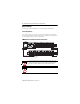
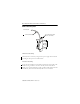
XM Dynamic Measurement Module Terminal Base 13 2. Slide the terminal base unit over leaving room for the side connector (B). 3. Hook the lip on the rear of the terminal base onto the top of the DIN rail, and rotate the terminal base onto the rail. 31883-M 4. Press down on the terminal base unit to lock the terminal base on the DIN rail.
XM Dynamic Measurement Module Terminal Base Interconnect Terminal Base Units Follow the steps below to install another terminal base unit. IMPORTANT Terminal base units are mounted left to right on the DIN rail. 1. Position the terminal base on the 35 x 7.5 mm DIN rail (A). 2. Make certain the side connector (B) is fully retracted into the base unit. 3. Slide the terminal base unit over tight against the neighboring terminal base.
XM Dynamic Measurement Module Terminal Base 15 Panel/Wall Mounting Installation on a wall or panel consists of: • laying out the drilling points on the wall or panel. • drilling the pilot holes for the mounting screws. • installing the terminal base units and securing them to the wall or panel. Follow these steps to install the terminal base on a wall or panel. 1. Lay out the required points on the wall/panel as shown in the drilling dimension drawing below. Maintain at least 25.4 mm (1.0 in.
XM Dynamic Measurement Module Terminal Base 5. Position the terminal base unit up tight against the neighboring terminal base; make certain the hook on the terminal base slides under the edge of the terminal base unit. 6. Gently push the side connector into the side of the neighboring terminal base to complete the backplane connection. 7. Secure the terminal base to the wall with two #6 self-tapping screws.
No. Desc. No Desc.
XM Dynamic Measurement Module Terminal Base Specifications XM Dynamic Measurement Terminal Base - 1440-TBS-J Attribute Value Enclosure Type Rating None (open-style) Isolation Voltage Established by installed module Voltage Ratings XM Bus Power Terminals I/O Terminals 24V DC, 3 A max, Class 2/SELV/PELV 24V DC, 3 A, Class 2/SELV/PELV 24V DC, 60 mA, Class 2/SELV/PELV Wire Size 0.34... 2.1 mm2 (22...14 AWG) solid or stranded copper wire rated at 75 °C (167 °F) or greater, 1.2 mm (3/64 in.
XM Dynamic Measurement Module Terminal Base 19 Environmental Specifications Attribute Value Non-operating temperature IEC 60068-2-1 (Test Ab, Unpackaged Non-operating Cold), IEC 60068-2-2 (Test Bb, Unpackaged Non-operating Dry Heat), IEC 60068-2-14 (Test Na, Unpackaged Non-operating Thermal Shock): -40…85 °C (-40…185 °F) Relative humidity IEC 60068-2-30 (Test Db, Unpackaged Damp Heat): 5…95% noncondensing Vibration IEC 60068-2-6 (Test Fc, Operating): 5 g @ 10…500 Hz Operating shock IEC 60068-2-27 (T
XM Dynamic Measurement Module Terminal Base Environmental Specifications Attribute Value Surge Transient Immunity IEC 61000-4-5: ±1 kV line-line (DM) and ±2 kV line-earth (CM) on power ports ±1 kV line-line (DM) and ±2 kV line-earth (CM) on signal ports ±2 kV line-earth (CM) on shielded ports Conducted RF Immunity IEC 61000-4-6: 10V rms with 1 kHz sine-wave 80% AM from 150 kHz…80 MHz Certifications Certifications(1) (when product is marked) c-UL-us Description UL Listed Industrial Control Equipmen
XM Dynamic Measurement Module Terminal Base 21 Certifications Certifications(1) (when product is marked) KC (1) Description Korean Registration of Broadcasting and Communications Equipment, compliant with: • Article 58-2 of Radio Waves Act, Clause 3 See the Product Certification link at http://www.ab.com for Declarations of Conformity, Certificates, and other certification details.
XM Dynamic Measurement Module Terminal Base Additional Resources These documents contain additional information concerning related products from Rockwell Automation. Resource Description XM Monitoring Modules Specifications Technical Data, publication 1440-TD001 Provides specifications for the 1440 series of Allen-Bradley® monitoring modules.
XM Dynamic Measurement Module Terminal Base 23 Notes: Publication ICM-IN003D-EN-P - March 2013
Rockwell Automation Support Rockwell Automation provides technical information on the Web to assist you in using its products. At http://www.rockwellautomation.com/support/, you can find technical manuals, a knowledge base of FAQs, technical and application notes, sample code and links to software service packs, and a MySupport feature that you can customize to make the best use of these tools.