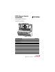
XM-947 Dynamic Vibration Terminal Base Catalog Number 1440-TB-H Installation Instructions For information about See page Important User Information 2 Safety Approvals 4 Power Requirements 6 Interconnect Limit 7 Wiring Requirements 7 Grounding Requirements 8 Mounting on the DIN Rail 12 Wiring 14 Agency Certification 21 Specifications 22
XM-947 Dynamic Vibration Terminal Base Important User Information Solid state equipment has operational characteristics differing from those of electromechanical equipment. Safety Guidelines for the Application, Installation and Maintenance of Solid State Controls (Publication SGI-1.1 available from your local Rockwell Automation sales office or online at http://literature.rockwellautomation.com) describes some important differences between solid state equipment and hard-wired electromechanical devices.
XM-947 Dynamic Vibration Terminal Base 3 ATTENTION Environment and Enclosure This equipment is supplied as “open type” equipment. It must be mounted within an enclosure that is suitably designed for those specific environmental conditions that will be present, and appropriately designed to prevent personal injury resulting from accessibility to live parts. The interior of the enclosure must be accessible only by the use of a tool.
XM-947 Dynamic Vibration Terminal Base Safety Approvals The following information applies when operating this equipment in hazardous locations. Informations sur l’utilisation de cet équipement en environnements dangereux. Products marked "CL I, DIV 2, GP A, B, C, D" are suitable for use in Class I Division 2 Groups A, B, C, D, Hazardous Locations and nonhazardous locations only. Each product is supplied with markings on the rating nameplate indicating the hazardous location temperature code.
XM-947 Dynamic Vibration Terminal Base 5 IMPORTANT Model XM-120 Wiring to or from this device, which enters or leaves the system enclosure, must utilize wiring methods suitable for Class I, Division 2 Hazardous Locations, as appropriate for the installation in accordance with the product drawings as indicated in the following table.
XM-947 Dynamic Vibration Terminal Base European Zone 2 Certification If appropriately marked, this equipment is intended for use in potentially explosive atmospheres as defined by European Union Directive 94/9/CE. Compliance with the Essential Health and Safety Requirements has been assured by compliance with EN 50021 (1999). IMPORTANT Observe the following additional Zone 2 certification requirements: • This equipment is not resistant to sunlight or other sources of UV radiation.
XM-947 Dynamic Vibration Terminal Base 7 Output Power 100 Watts Maximum (~4A @ 24Vdc) Static Regulation ± 2% Dynamic Regulation ± 3% Ripple < 100mVpp Output Noise Per EN50081-1 Overshoot < 3% at turn-on, < 2% at turn-off Hold-up Time As required (typically 50mS at full rated load * When a fused supply is used the fuse must be a 5 amp, listed, fast acting fuse such as provided by Allen-Bradley part number 1440-5AFUSEKIT.
XM-947 Dynamic Vibration Terminal Base • 14 to 22 AWG copper conductors without pretreatment; 8 AWG required for grounding the DIN rail for electromagnetic interference (emi) purposes • Recommended strip length 8 millimeters (0.31 inches) • Minimum insulation rating of 300V • Soldering the conductor is forbidden • Wire ferrules can be used with stranded conductors; copper ferrules recommended ATTENTION See the XM Documentation and Configuration Utility CD for Hazardous Locations installation drawings.
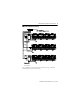
XM-947 Dynamic Vibration Terminal Base 9 XM System DIN Rail Grounding 1 1440-VST02-01RA DYNAMIC MEASUREMENT 1440-REX00-04RD EXPANSION RELAY 1440-VST02-01RA DYNAMIC MEASUREMENT 1440-REX00-04RD EXPANSION RELAY Power Supply 1440-RMA00-04RC MASTER RELAY 1 1440-REX00-04RD EXPANSION RELAY 1440-VST02-01RA DYNAMIC MEASUREMENT 1440-TSP02-01RB POSITION 1440-REX00-04RD EXPANSION RELAY 1440-REX00-04RD EXPANSION RELAY 1440-VST02-01RA DYNAMIC MEASUREMENT 1440-REX00-04RD EXPANSION RELAY Power Supply 1 U
XM-947 Dynamic Vibration Terminal Base DIN Rail Grounding Block 24V Common Grounding 24V to the XM module must be grounded. When two or more power supplies power the XM system, ground the 24 V Commons at a single point, such as the ground bus bar. IMPORTANT IMPORTANT If it is not possible or practical to ground the -24Vdc supply, then it is possible for the system to be installed and operate ungrounded.
XM-947 Dynamic Vibration Terminal Base 11 Transducer Grounding Make certain the transducers are electrically isolated from earth ground. Cable shields must be grounded at one end of the cable, and the other end left floating or not connected. It is recommended that where possible, the cable shield be grounded at the XM terminal base (Chassis terminal) and not at the transducer. DeviceNet Grounding The DeviceNet network is functionally isolated and must be referenced to earth ground at a single point.
XM-947 Dynamic Vibration Terminal Base Mounting on the DIN Rail You can also mount the terminal base to a grounded mounting plate. Refer to the XM Module User Guide for details. ATTENTION The XM-947 makes a chassis ground connection through the DIN rail. Use zinc plated, yellow chromated steel DIN rail to assure proper grounding. Using other DIN rail materials (e.g. aluminum, plastic, etc.) which can corrode, oxidize or are poor conductors can result in improper or intermittent platform grounding. 1.
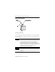
XM-947 Dynamic Vibration Terminal Base 13 3. Hook the lip on the rear of the terminal base onto the top of the DIN rail, and rotate the terminal base onto the rail. 4. Press down on the terminal base unit to lock the terminal base on the DIN rail. If the terminal base does not lock into place, use a screwdriver or similar device to open the locking tab, press down on the terminal base until flush with the DIN rail and release the locking tab to lock the base in place. 5.
XM-947 Dynamic Vibration Terminal Base 4. Press down on the terminal base unit to lock the terminal base on the DIN rail. If the terminal base does not lock into place, use a screwdriver or similar device to open the locking tab, press down on the terminal base until flush with the DIN rail and release the locking tab to lock the base in place. 5. Gently push the side connector into the side of the neighboring terminal base to complete the backplane connection.
XM-947 Dynamic Vibration Terminal Base 15 Terminal Assignments WARNING EXPLOSION HAZARD Do not disconnect equipment unless power has been removed or the area is known to be nonhazardous. Do not disconnect connections to this equipment unless power has been removed or the area is known to be nonhazardous. Secure any external connections that mate to this equipment by using screws, sliding latches, threaded connectors, or other means provided with this product.
XM-947 Dynamic Vibration Terminal Base No. Description No.
XM-947 Dynamic Vibration Terminal Base 17 XM-161 Direct Vibration with 4-20mA Module Terminal Assignments No. Description No.
XM-947 Dynamic Vibration Terminal Base No. Description No. Description 24 Channel 3 Buffer Out 50 Channels 4...6 4-20mA V+ 25 Channel 4 Signal In 51 Channels 4...6 4-20mA V+ IMPORTANT The DeviceNet power circuit through the XM module interconnect, which is rated at only 300mA, is not intended or designed to power DeviceNet loads. Doing so could damage the module or terminal base. To preclude this possibility, even unintentionally, it is recommended that DeviceNet V+ be left unconnected.
XM-947 Dynamic Vibration Terminal Base 19 XM-162 Direct Vibration with Power Module Terminal Assignments No Description No. Description 0 Chassis 26 Channel 4 Buffer Out 1 Chassis 27 Channel 5 Signal In 2 Chassis 28 Channel 5 Buffer Out 3 Signal Common 29 Channel 6 Signal In 4 Signal Common 30 Channel 6 Buffer Out 5 Signal Common 31 Channels 4...6 -24V Prox Probe Power 6 Signal Common 32 Channels 4...6 -24V Prox Probe Power 7 Signal Common 33 Channels 4...
XM-947 Dynamic Vibration Terminal Base No Description No. Description 24 Channel 3 Buffer Out 50 Circuit Ground 25 Channel 4 Signal In 51 Circuit Ground IMPORTANT The DeviceNet power circuit through the XM module interconnect, which is rated at only 300mA, is not intended or designed to power DeviceNet loads. Doing so could damage the module or terminal base. To preclude this possibility, even unintentionally, it is recommended that DeviceNet V+ be left unconnected.
XM-947 Dynamic Vibration Terminal Base 21 Agency Certification (when product marked) UL UL Listed for Ordinary Locations UL UL Listed for Class I, Division 2 Group A, B, C, and D Hazardous Locations CSA CSA Certified Process Control Equipment CSA CSA Certified Process Control Equipment for Class I, Division 2 Group A, B, C, and D Hazardous Locations EEX2 European Union 94/9/EEC ATEX Directive, compliant with EN 50021; Potentially Explosive Atmospheres, Protection “n” CE2 European Union 89/336/EE
XM-947 Dynamic Vibration Terminal Base Specifications The following table lists the technical specifications for the XM-947 Dynamic Vibration Terminal Base. Product Feature Specification Power Supply Voltage +18 to +32V dc XM-160 and XM-162 Modules Maximum current: 190 mA @ 24V dc Maximum Power Dissipation: 4.56 Watts @ 24V dc (4.3 Watts @ 18V dc, 4.
XM-947 Dynamic Vibration Terminal Base 23 Publication GMSI10-IN027A-EN-P - May 2010
Rockwell Automation Support Rockwell Automation provides technical information on the Web to assist you in using its products. At http://www.rockwellautomation.com/support/, you can find technical manuals, a knowledge base of FAQs, technical and application notes, sample code and links to software service packs, and a MySupport feature that you can customize to make the best use of these tools.