
Manual
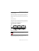

18 XM-941 Speed/Position Terminal Base
Publication GMSI10-IN021A-EN-P - May 2010
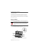
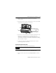
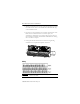
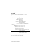
XM-320 Position Module Terminal Assignments
No. Description No. Description
0 Transducer 1 connection (+) 26 DeviceNet V (+) (red wire) (Optional,
see IMPORTANT note below)
1 Transducer 2 connection (+) 27 DeviceNet V (-) (black wire)
2 Protected output 1 (+) 28 24V common
3 Protected output 2 (+) 29 4-20mA 2 (+)
4 No connection 30 4-20mA 2 (-)
5 No connection 31 Chassis
6 Transducer power supply
output (+)
32 Chassis
7 TxD 33 Chassis
8 RxD 34 Chassis
9 XRTN 35 Chassis
10 Chassis ground 36 Chassis
11 4-20mA 1 (+) 37 Chassis
12 4-20mA 1 (-) 38 Chassis
13 Chassis 39 Set Point Multiplication
14 Chassis 40 Switch return
15 Chassis 41 Reset relay
16 Transducer 1 connection (-) 42 24V in 2
17 Transducer 2 connection (-) 43 24V common
18 Protected output 1 (-) 44 24V in 1
19 Protected output 2 (-) 45 24 V common
20 No connection 46 Relay N.C. contact 1
21 No connection 47 Relay common contact 1
22 Transducer power return 48 Relay N.O. contact 1
23 CAN_High (white wire) 49 Relay N.O. contact 2
24 CAN_Low (blue wire) 50 Relay common contact 2
25 +24V out 51 Relay N.C. contact 2