
Owner manual


Publication GMSI10-UM001C-EN-E - June 2011
6 Introduction
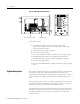
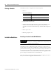
Figure 1.1 XM-720 Front and Side View
Each monitor offers:
• two vibration transducer connections (eddy current probes,
accelerometers, velocity sensors, AC voltage output or DC voltage
output measurement devices)
• one tachometer input signal connection
• remote relay reset connection
• three relays available for module or transducer fault, warning and trip
• isolated 4-20mA per channel into a maximum load of 250 ohm
• three buffered output signals on the front panel BNC connectors
• two front panel digital meters
• four front panel LED indicators (module, transducer, warning, and trip
status)
System Description
The concept of machine monitoring is quite simple. During normal operation,
the machine’s "vital signs" remain within relatively narrow ranges. If a
mechanical problem develops, it will be reflected as a change in one or more of
these vital signs. This change will be detected by the XM-720 and cause an
alarm.
The monitoring system consists of a number of transducers connected to the
XM-720. The transducers installed on the machine convert the "vital signs" to
electrical signals that are transmitted to the XM-720 monitor.
The XM-720 accepts the signals from the transducers, processes and measures
the signals, and closes electrical relay contacts if one of the signals increases
too much. The relays can be connected to annunciators or to automatic
machine controls.
123456789100
16 17 1819 2021 22 2324 25 2627 2829 3031 3233
34 35 3637 38 3940 4142 4344 4546 4748 49 5051
11 12 1314 15
123456789100
16 17 1819 2021 22 2324 2526 2728 2930 3132 33
34 35 3637 38 3940 4142 4344 4546 4748 4950 51
11 12 1314 15
Warning
Trip
Module
Fault
Xdcr
Fault
Reset
Tacho
CH 2CH 1
%
0
25
50
75
%
100
0
25
50
75
100
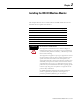
XM-120/121/122 module XM-441 module