
Owner manual


57 Publication GMSI10-UM001C-EN-E - June 2011
Appendix
B
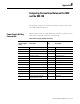
Comparing Connections Between the 5802
and the XM-720
This appendix compares the connections between the 5802 monitor to those
of the XM-720 Machine Monitor.
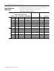
Power Supply & Relay
Connections
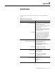
Table B.1 defines the power supply, alarm relay and control connectors for the
5802, and the comparable connectors on the XM-720.
Table A.1 Power Supply & Relay Connections
5802 XM-720
Power Supply &
Relay
Description TB1 Description
1 Line (Black) L AC Input Line
2, 3, 4, or 5 Neutral N AC Input Neutral
Chassis ground lug Ground E AC Earth Ground
6 Close on Trip Alarm 10 Trip Relay NO
7 Trip Alarm Common 11 Trip Relay Common
8 Open on Trip Alarm 12 Trip Relay NC
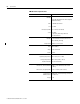
9 Close on Warning Alarm 7 Warning Relay NO
10 Warning Alarm Common 8 Warning Relay Common
11 Open on Warning Alarm 9 Warning Relay NC
12 Open on Fault Alarm 4 Fault Relay NO
13 Fault Alarm Common 5 Fault Relay Common
14 Close on Fault Alarm 6 Fault Relay NC
15 Remote Reset Momentary Switch 13 Reset Relay Switch
16 Return for Remote Reset and
Setpoint Multiplier Switch
14 Switch RTN