
Owner manual


Publication GMSI10-UM001C-EN-E - June 2011
52 Configuring the XM-720
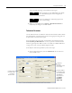
2. Enter or select the desired parameters to define the characteristics of the
tachometer signal. This includes:
• the minimum and maximum expected DC voltage
• the DC bias time constant
• the number of tachometer signal pulses per revolution of the shaft
• the amount of hysteresis around the trigger threshold
3. When you are finished, choose Device > Download to Device to
download your changes to the XM module.
TIP
Refer to Chapter 3 in the XM Module User Guide
for a detailed description of the configuration
parameters.
TIP
Press F1 to display the online help topic for the
current tab or dialog.